Nissan Rogue (T33) 2021-Present Service Manual: Dtc/circuit Diagnosis :: B2090-14 Nats Antenna Amp.
DTC Description
DTC DETECTION LOGIC
| DTC No. |
CONSULT screen items (Trouble diagnosis content) | DTC detecting condition | |
|---|---|---|---|
| B2090–14 |
NATS antenna amp. (Nissan anti-theft system antenna amplifier) |
Diagnosis condition | Work supports ‟Inside/outside antenna diagnosis”: activated |
| Signal (terminal) | NATS antenna amp. signal | ||
| Threshold | Inactive communication between NATS antenna amp. and Intelligent Key unit | ||
| 1 second or less | |||
POSSIBLE CAUSE
-
Harness or connectors
(NATS antenna amp. circuit is open or shorted.)
-
Push-button ignition switch (NATS antenna amp.)
-
Intelligent Key unit
FAIL-SAFE
Diagnosis delay time
—
CONFIRMATION PROCEDURE
DTC CONFIRMATION
 CONSULT
-
Select “Inside/outside antenna diagnosis” in “Work supports” mode of “INTELLIGENT KEY”.
-
Select “Self diagnosis result” mode of “INTELLIGENT KEY”.
Is the DTC detected?
YES>>Refer to DTC Diagnosis Procedure.
NO-1>>To check malfunction symptom before repair: Refer to Intermittent Incident.
NO-2>>Confirmation after repair: Inspection End.
DTC Diagnosis Procedure
CHECK NATS ANTENNA AMP. COMMUNICATION SIGNAL
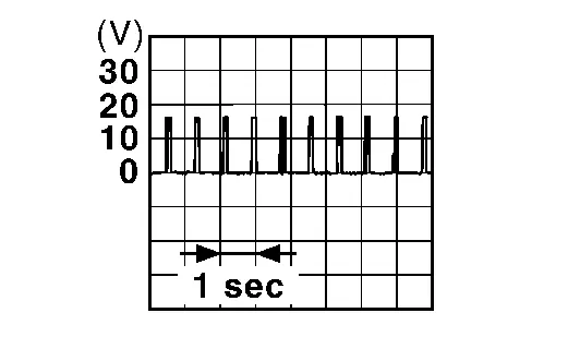
Check signal between push-button ignition switch harness connector and ground using an oscilloscope.
| (+) | (–) | Condition |
Signal (Reference value) | ||
|---|---|---|---|---|---|
| Push-button ignition switch | |||||
| Connector | Terminal | ||||
| M17 | 2 | Ground | Intelligent Key battery is removed and brake pedal is depressed | When a registered Intelligent Key backside is contacted to push-button ignition switch | 0 V |
| Other than above |
|
||||
| 3 | When a registered Intelligent Key backside is contacted to push-button ignition switch | 0 V | |||
| Other than above |
|
||||
Is the inspection result normal?
YES>>GO TO 3.
NO>>GO TO 2.
CHECK NATS ANTENNA AMP. COMMUNICATION SIGNAL CIRCUIT
-
Ignition switch OFF.
-
Disconnect Intelligent Key unit connector and push-button ignition switch connector.
-
Check continuity between push-button ignition switch harness connector and Intelligent Key unit harness connector.
USA production Push-button ignition switch Intelligent Key unit Continuity Connector Terminal Connector Terminal M17 2 M184 19 Yes 3 20 Japan production Push-button ignition switch Intelligent Key unit Continuity Connector Terminal Connector Terminal M17 2 M189 19 Yes 3 20 -
Check continuity between push-button ignition switch harness connector and ground.
Push-button ignition switch — Continuity Connector Terminal M17 2 Ground No 3
Is the inspection result normal?
YES>>GO TO 3.
NO>>Repair or replace harness.
REPLACE PUSH-BUTTON IGNITION SWITCH
Replace push-button ignition switch. Refer to Removal and Installation.
Is the inspection result normal?
YES>>Inspection End.
NO>>GO TO 4.
REPLACE INTELLIGENT KEY UNIT
Replace Intelligent Key unit. Refer to Removal and Installation.
>>
Inspection End.
Other materials:
Plug
Description
Replace the O-ring if oil leaks from the plug.
Exploded View
1.
Plug
2.
O-ring
3.
Plug
4.
O-ring
5.
O-ring
6.
Overflow plug
7.
O-ring
8.
Transaxle assembly
: N·m (kg-m, ft-lb) : N·m (kg-m, in-lb) : Always replace ...
Its Can Communication 4 Circuit
Diagnosis Procedure
CHECK NETWORK DIAGNOSIS
Check the "Network diagnosis" results from CONSULT to see that the diagnostic CAN communication circuit have no malfunction.
Are the diagnostic CAN communication circuit normal?
YES>>
GO TO 2.
NO>>
Check and repair diagnostic CAN commu ...
Dtc/circuit Diagnosis. U1327-52 Mac Key Update
DTC Description
DTC DETECTION LOGIC DTC No.
CONSULT screen items
(Trouble diagnosis content) DTC Detection Condition
U1327-52
MAC key update
(Message authentication code key update)
Diagnosis condition
-
Signal (terminal)
-
Threshold
MAC key writing is incomplete. ...