Nissan Rogue (T33) 2021-Present Service Manual: Dtc/circuit Diagnosis :: B203d-14 Inside Antenna
DTC Description
DTC DETECTION LOGIC
| DTC No. |
CONSULT screen items (Trouble diagnosis content) | DTC detecting condition | |
|---|---|---|---|
| B203D-14 |
Inside antenna (Inside antenna) |
Diagnosis condition | Work supports ŌĆ£Inside/outside antenna diagnosisŌĆØ: activated |
| Signal (terminal) | Inside key antenna signal (Intelligent Key unit connector terminal: 33, 34) | ||
| Threshold | Inside key antenna circuit is shorted to ground | ||
| Diagnosis delay time | 1 second or less | ||
POSSIBLE CAUSE
-
Intelligent Key unit
-
Inside key antenna
-
Harness or connector (inside key antenna circuit is open or shorted)
FAIL-SAFE
ŌĆō
DTC CONFIRMATION PROCEDURE
DTC CONFIRMATION
 CONSULT
-
Select ŌĆ£Inside/outside antenna diagnosisŌĆØ in ŌĆ£Work supportsŌĆØ mode of ŌĆ£INTELLIGENT KEYŌĆØ.
-
Select ŌĆ£Self diagnosis resultŌĆØ mode of ŌĆ£INTELLIGENT KEYŌĆØ.
Is DTC detected?
YES>>Refer to DTC Diagnosis Procedure.
NO-1>>To check malfunction symptom before repair: Refer to Intermittent Incident.
NO-2>>Confirmation after repair: Inspection End.
DTC Diagnosis Procedure
CHECK INSIDE KEY ANTENNA INPUT SIGNAL 1
-
Ignition switch ON.
-
Check signal between Intelligent Key unit harness connector and ground using oscilloscope.
(+) (ŌĆō) Condition Signal
(Reference value)Intelligent Key unit Connector Terminal M184 33 Ground Press push-button ignition switch When Intelligent Key is in the passenger compartment 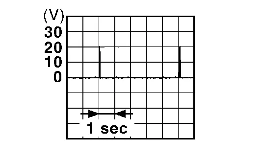
When Intelligent Key is not in the passenger compartment 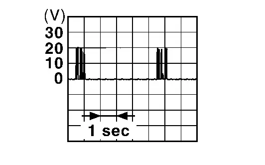
34 When Intelligent Key is in the passenger compartment When Intelligent Key is not in the passenger compartment
Is the inspection result normal?
YES>>Replace Intelligent Key unit. Refer to Removal and Installation.
NO>>GO TO 2.
CHECK INSIDE KEY ANTENNA CIRCUIT
-
Ignition switch OFF.
-
Disconnect Intelligent Key unit connector and inside key antenna connector.
-
Check continuity between Intelligent Key unit harness connector and inside key antenna harness connector.
Japan production models Intelligent Key unit Inside key antenna Continuity Connector Terminal Connector Terminal M184 33 B77 2 Yes 34 1 USA production models Intelligent Key unit Inside key antenna Continuity Connector Terminal Connector Terminal M184 33 B83 2 Yes 34 1 -
Check continuity between Intelligent Key unit harness connector and ground.
USA production models Intelligent Key unit ŌĆö Continuity Connector Terminal M184 33 Ground No 34 Japan production models Intelligent Key unit ŌĆö Continuity Connector Terminal M184 33 Ground No 34
Is the inspection result normal?
YES>>GO TO 3.
NO>>Repair or replace harness.
CHECK INSIDE KEY ANTENNA INPUT SIGNAL 2
-
Replace inside key antenna. (New antenna or other antenna)
-
Connect Intelligent Key unit connector and inside key antenna connector.
-
Ignition switch ON.
-
Check signal between Intelligent Key unit harness connector and ground using oscilloscope.
(+) (ŌĆō) Condition Signal
(Reference value)Intelligent Key unit Connector Terminal M184 33 Ground Press push-button ignition switch When Intelligent Key is in the passenger compartment When Intelligent Key is not in the passenger compartment 34 When Intelligent Key is in the passenger compartment When Intelligent Key is not in the passenger compartment
Is the inspection result normal?
YES>>Replace inside key antenna. Refer to Removal and Installation (Japan production models) or Removal and Installation (USA production models).
NO>>Replace Intelligent Key unit. Refer to Removal and Installation.
Other materials:
Diagnosis System (hvac)
CONSULT Function
CONSULT performs the following functions via CAN communication with A/C amp. Diagnosis mode Function
Self diagnosis result
Display non-network DTC which A/C amp. memorizes
ECU identification
The A/C amp. part number is displayed
Active Test
The signals used t ...
Removal and Installation. Front Suspension Member
Exploded View
1.
Front suspension member
2.
Member stay
ŌĆö
ŌĆö
: Nissan Ariya Vehicle front
: N┬Ęm (kg-m, ft-lb)
Removal and Installation
REMOVALRemove tires. Refer to Removal & Installation.
Remove engine under cover. Refer toRemoval and Installation.
...
Precaution. Precautions
Precaution for Supplemental Restraint System (SRS) "AIR BAG" and "SEAT BELT PRE-TENSIONER"
The Supplemental Restraint System such as ŌĆ£AIR BAGŌĆØ and ŌĆ£SEAT BELT
PRE-TENSIONERŌĆØ, used along with a front seat belt, helps to reduce the
risk or severity of injury to the driver and front passeng ...