Nissan Rogue Service Manual: Door switch
WITH INTELLIGENT KEY
WITH INTELLIGENT KEY : Component Function Check
1.CHECK FUNCTION
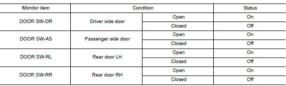
- Select "DOOR LOCK" of "BCM" using CONSULT.
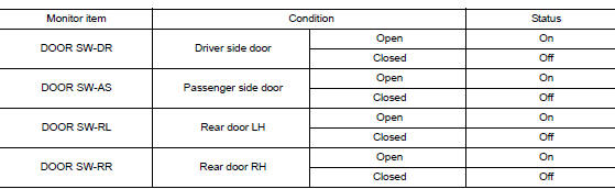
- Select "DOOR SW-DR", "DOOR SW-AS", "DOOR SW-RL", "DOOR SW-RR", in "Data Monitor" mode.
- Check that the function operates normally according to the following conditions.
Is the inspection result normal? YES >> Door switch is OK.
NO >> Refer to RF-34, "WITH INTELLIGENT KEY : Diagnosis Procedure".
WITH INTELLIGENT KEY : Diagnosis Procedure
Regarding Wiring Diagram information, refer to DLK-69, "Wiring Diagram".
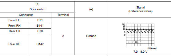
1.CHECK DOOR SWITCH INPUT SIGNAL
- Turn ignition switch OFF.
- Disconnect malfunctioning door switch connector.
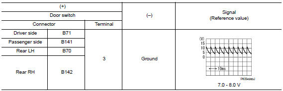
- Check signal between malfunctioning door switch harness connector and ground using oscilloscope.
Is the inspection result normal? YES >> GO TO 3.
NO >> GO TO 2.
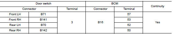
2.CHECK DOOR SWITCH CIRCUIT
- Disconnect BCM connector.
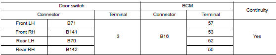
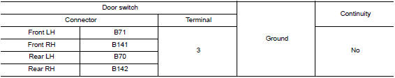
- Check continuity between door switch harness connector and BCM harness connector.
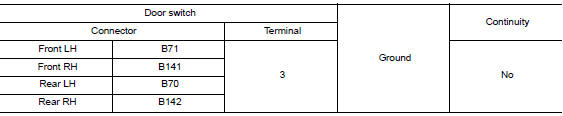
- Check continuity between door switch harness connector and ground.
Is the inspection result normal? YES >> Replace BCM. Refer to BCS-75, "Removal and Installation".
NO >> Repair or replace harness.
3.CHECK DOOR SWITCH
Refer to RF-35, "WITH INTELLIGENT KEY : Component Inspection".
Is the inspection result normal? YES >> GO TO 4.
NO >> Replace malfunctioning door switch. Refer to DLK-269, "Removal and Installation".
4.CHECK INTERMITTENT INCIDENT
Refer to GI-41, "Intermittent Incident".
>> Inspection End.
WITH INTELLIGENT KEY : Component Inspection
1.CHECK DOOR SWITCH
- Turn ignition switch OFF.
- Disconnect malfunctioning door switch connector.
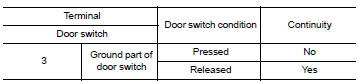
- Check continuity between door switch terminals.
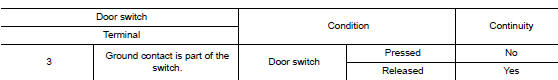
Is the inspection result normal? YES >> Inspection End.
NO >> Replace malfunctioning door switch. Refer to DLK-269, "Removal and Installation".
WITHOUT INTELLIGENT KEY
WITHOUT INTELLIGENT KEY : Description
Detects door open/close condition.
WITHOUT INTELLIGENT KEY : Component Function Check
1.CHECK FUNCTION
- Select "DOOR LOCK" of BCM using CONSULT.
- Select "DOOR SW-DR", "DOOR SW-AS", "DOOR SW-RL", "DOOR SW-RR", in Data Monitor mode.
- Check that the function operates normally according to the following conditions.
Is the inspection result normal? YES >> Door switch is OK.
NO >> Refer to RF-36, "WITHOUT INTELLIGENT KEY : Diagnosis Procedure".
WITHOUT INTELLIGENT KEY : Diagnosis Procedure
Regarding Wiring Diagram information, refer to DLK-293, "Wiring Diagram".
1.CHECK DOOR SWITCH INPUT SIGNAL
- Turn ignition switch OFF.
- Disconnect malfunctioning door switch connector.
- Check signal between malfunctioning door switch harness connector and ground using oscilloscope.
Is the inspection result normal? YES >> GO TO 3.
NO >> GO TO 2.
2.CHECK DOOR SWITCH CIRCUIT
- Disconnect BCM connector.
- Check continuity between door switch harness connector and BCM harness connector.
- Check continuity between door switch harness connector and ground.
Is the inspection result normal? YES >> Replace BCM. Refer to BCS-135, "Removal and Installation".
NO >> Repair or replace harness.
3.CHECK DOOR SWITCH
Refer to RF-35, "WITH INTELLIGENT KEY : Component Inspection".
Is the inspection result normal? YES >> GO TO 4.
NO >> Replace malfunctioning door switch. Refer to DLK-385, "Removal and Installation".
4.CHECK INTERMITTENT INCIDENT
Refer to GI-41, "Intermittent Incident".
>> Inspection End.
WITHOUT INTELLIGENT KEY : Component Inspection
1.CHECK DOOR SWITCH
- Turn ignition switch OFF.
- Disconnect door switch connector.
- Check door switch.
Is the inspection result normal? YES >> Inspection End.
NO >> Replace malfunctioning door switch. Refer to DLK-385, "Removal and Installation".
 Moonroof switch
Description
Transmits switch operation signal to moonroof motor and sunshade motor
assembly.
Diagnosis Procedure
Regarding Wiring Diagram information, refer to RF-17, "Wiring Diagram".
...

Other materials:
Under cover
Exploded View
Floor under cover (RH)
Engine under cover
Floor under cover (LH)
ENGINE UNDER COVER
ENGINE UNDER COVER : Removal and Installation
REMOVAL
Remove engine under cover clips.
Remove engine under cover.
INSTALLATION
Installation is in the reverse ord ...
CAN system (type 5)
MAIN LINE BETWEEN IPDM-E AND DLC CIRCUIT
Diagnosis Procedure
1.CHECK CONNECTOR
Turn the ignition switch OFF.
Disconnect the battery cable from the negative terminal.
Check the following terminals and connectors for damage, bend and
loose connection (connector side
an ...
Corrosion protection
Description
To provide improved corrosion prevention, the following anti-corrosive
measures have been implemented in
NISSAN production plants. When repairing or replacing body panels, it is
necessary to use the same anti-corrosive
measures.
ANTI-CORROSIVE PRECOATED STEEL (GALVANNEALED STEEL) ...
