Nissan Rogue Service Manual: Moonroof switch
Description
Transmits switch operation signal to moonroof motor and sunshade motor assembly.
Diagnosis Procedure
Regarding Wiring Diagram information, refer to RF-17, "Wiring Diagram".
1.CHECK MOONROOF SWITCH INPUT SIGNAL
- Turn ignition switch ON.
- Check voltage between moonroof motor assembly harness connector and ground.
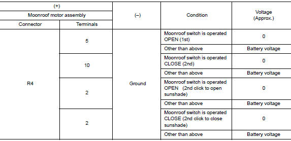
Is the inspection result normal? YES >> Inspection End.
NO >> GO TO 2.
2.CHECK MOONROOF SWITCH CIRCUIT
- Turn ignition switch OFF.
- Disconnect moonroof motor assembly connector and moonroof switch connector.
- Check continuity between moonroof motor assembly harness connector and moonroof switch harness connector.
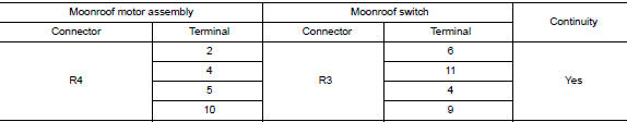
- Check continuity between moonroof motor assembly harness connector and ground.
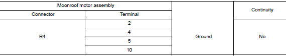
Is the inspection result normal? YES >> GO TO 3.
NO >> Repair or replace the harness.
3.CHECK MOONROOF SWITCH GROUND CIRCUIT
Check continuity between moonroof switch harness connector and ground.
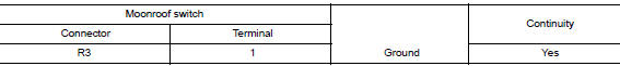
Is the inspection result normal? YES >> GO TO 4.
NO >> Repair or replace the harness.
4.CHECK MOONROOF SWITCH
Check moonroof switch.
Refer to RF-32, "Component Inspection".
Is the inspection result normal? YES >> GO TO 5.
NO >> Replace moonroof switch. Refer to RF-64, "Removal and Installation".
5.CHECK INTERMITTENT INCIDENT
Refer to GI-41, "Intermittent Incident".
>> Inspection End.
Component Inspection
MOONROOF SWITCH
1. CHECK MOONROOF SWITCH
- Turn ignition switch OFF.
- Disconnect moonroof switch.
- Check continuity between moonroof switch terminals.
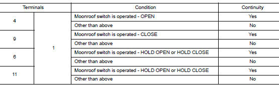
Is the inspection result normal? YES >> Moonroof switch is OK.
NO >> Replace moonroof switch. Refer to RF-64, "Removal and Installation".
 Power supply and ground circuit
BCM (BODY CONTROL SYSTEM) (WITH INTELLIGENT KEY SYSTEM)
BCM (BODY CONTROL SYSTEM) (WITH INTELLIGENT KEY SYSTEM) : Diagnosis
Procedure
Regarding Wiring Diagram information, refer to BCS-50, "Wi ...
 Door switch
WITH INTELLIGENT KEY
WITH INTELLIGENT KEY : Component Function Check
1.CHECK FUNCTION
Select "DOOR LOCK" of "BCM" using CONSULT.
Select "DOOR SW-DR", ...
Other materials:
C1704, C1705, C1706, C1707 low tire pressure
DTC Logic
NOTE:
The Signal Tech II Tool [- (J-50190)] can be used to perform the following
functions. Refer to the Signal Tech II
User Guide for additional information.
Activate and display TPMS sensor IDs
Display tire pressure reported by the TPMS sensor
Read TPMS DTC ...
Vehicle information
Identification information
Model Variation
FWD Model
AWD Model
Prefix and Suffix Designations
Identification Number
Air conditioner specification label
Emission control information label
Vehicle identification number chassis
number (center of bulkhead) ...
Avoiding collision and rollover
WARNINGFailure to operate this vehicle in a safe
and prudent manner may result in loss of
control or an accident.
Be alert and drive defensively at all times. Obey
all traffic regulations. Avoid excessive speed,
high speed cornering, or sudden steering maneuvers,
because these ...
