Nissan Rogue Owners Manual: Difference between predictive and actual distances
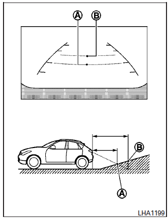
Backing up on a steep uphill
When backing up the vehicle up a hill, the distance guide lines and the vehicle width guide lines are shown closer than the actual distance.
For example, the display shows 3 ft (1.0 m) to the place A , but the actual 3 ft (1.0 m) distance on the hill is the place B . Note that any object on the hill is further than it appears on the monitor.
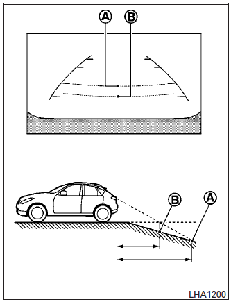
Backing up on a steep downhill
When backing up the vehicle down a hill, the distance guide lines and the vehicle width guide lines are shown farther than the actual distance.
For example, the display shows 3 ft (1.0 m) to the place A , but the actual 3 ft (1.0 m) distance on the hill is the place B . Note that any object on the hill is closer than it appears on the monitor
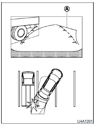
Backing up near a projecting object
The predicted course lines A do not touch the object in the display. However, the vehicle may hit the object if it projects over the actual backing up course.
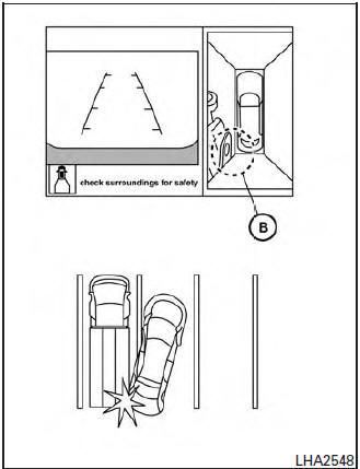
Backing up near a projecting object
There may be a small distance visible between the vehicle and the object in the bird-eye view on the display B .
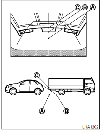
Backing up behind a projecting object
The position C is shown farther than the position B in the display. However, the position C is actually at the same distance as the position A .
The vehicle may hit the object when backing up to the position A if the object projects over the actual backing up course.
 Available views
WARNING
The distance guide line and the vehicle
width line should be used as a reference
only when the vehicle is on a paved,
level surface. The distance viewed on
the ...
 How to switch the display
With the ignition switch in the ON position, press
the CAMERA button or move the shift lever to the
R (Reverse) position to operate the Around View
Monitor.
The Around View Monitor displays diff ...
Other materials:
Oil pan
Exploded View
COMPONENT PARTS LOCATION
Transaxle assembly
Oil pan gasket
Oil pan
Drain plug
Drain plug gasket
Magnet
Overflow plug
O-ring
Always replace after every
disassembly.
: N┬Ęm (kg-m, ft-lb)
: N┬Ęm (kg-m, in-lb)
: Apply CVT fluid
Removal and Installation ...
Power window relay
Description
Power is supplied to the main power window and door lock/unlock with BCM
control.
Component Function Check
1. CHECK POWER WINDOW RELAY POWER SUPPLY CIRCUIT
Check that an operation noise of power window relay [located behind the A/C
switch assembly (automatic A/
C) or Front air c ...
Moonroof motor assembly
Exploded View
Panoramic roof glass
Glass lid
Side trim covers (LH/RH)
Front drain hose front (LH/RH)
Moonroof motor assembly
Sunshade motor assembly
Moonroof front bracket (LH/RH)
Moonroof rear bracket (LH/RH)
Drain hose rear (LH/RH)
Moonroof unit assembly ...
