Nissan Rogue Owners Manual: Available views
WARNING
|
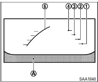
Front view
Front and rear view
Guiding lines, which indicate the vehicle width and distance to objects with reference to the vehicle body line A , are displayed on the monitor.
Distance guide lines:
Indicate distances from the vehicle body:
- Red line 1 : approximately 1.5 ft (0.5 m)
- Yellow line 2 : approximately 3 ft (1 m)
- Green line 3 : approximately 7 ft (2 m)
- Green line 4 : approximately 10 ft (3 m)
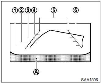
Rearview
Vehicle width guide lines 5 :
Indicate the vehicle width when backing up.
Predictive course lines 6 :
Indicate the predictive course when operating the vehicle. The predictive course lines will be displayed on the monitor when the steering wheel is turned. The predictive course lines will move depending on how much the steering wheel is turned and will not be displayed while the steering wheel is in the neutral position.
The front view will not be displayed when the vehicle speed is above 6 mph (10 km/h).
NOTE: When the monitor displays the front view and the steering wheel turns about 90 degrees or less from the neutral position, both the right and left predictive course lines 6 are displayed. When the steering wheel turns about 90 degrees or more, a line is displayed only on the opposite side of the turn.
WARNING
|
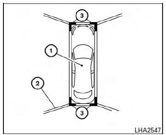
BirdŌĆÖs-eye view
The birdŌĆÖs-eye view shows the overhead view of the vehicle, which helps confirm the vehicle position and the predicted course to a parking space.
The vehicle icon 1 shows the position of the vehicle. Note that the distance between objects viewed in the birdŌĆÖs-eye view differs from the actual distance.
The areas that the cameras cannot cover 2 are indicated in black.
After the ignition switch is placed in the ON position, the non-viewable area 2 is highlighted in yellow for 3 seconds after the birdŌĆÖs-eye view is displayed. In addition, the non-viewable corners are displayed in red and blink for the first 3 seconds 3 to remind the driver to be cautious.
WARNING
|
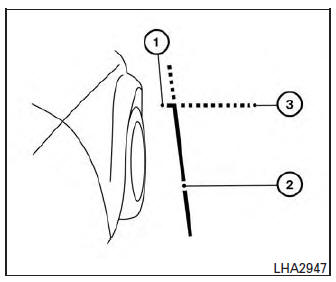
Front-side view
Guiding lines:
Guiding lines that indicate the width and the front end of the vehicle are displayed on the monitor.
The front-of-vehicle line 1 shows the front part of the vehicle.
The side-of-vehicle line 2 shows the vehicle width including the outside mirror.
The extensions 3 of both the front 1 and side 2 lines are shown with a green dotted line.
CAUTION
|
 Around View® Monitor (if so equipped)
With the ignition switch in the ON position, press
the CAMERA button or move the shift lever to the
R (Reverse) position to operate the Around View
Monitor. The monitor displays various views of
t ...
 Difference between predictive and actual
distances
Difference between predictive and actual
distances
Backing up on a steep uphill
When backing up the vehicle up a hill, the distance
guide lines and the vehicle width guide
lines are shown closer than the actual distance.
For example, the dis ...
Other materials:
Wiring diagram
POWER DOOR LOCK SYSTEM
Wiring Diagram
INTELLIGENT KEY SYSTEM
Wiring Diagram
AUTOMATIC BACK DOOR SYSTEM
Wiring Diagram
HOMELINK UNIVERSAL TRANSCEIVER
Wiring D ...
Basic inspection
DIAGNOSIS AND REPAIR WORKFLOW
Work Flow
OVERALL SEQUENCE
DETAILED FLOW
1.GET INFORMATION FOR SYMPTOM
Get detailed information from the customer about the symptom (the condition
and the environment when the
incident/malfunction occurred).
>> GO TO 2.
2.CONFIRM THE SYMPTOM
Try t ...
Moonroof does not operate properly
Diagnosis Procedure
1. CHECK BCM POWER SUPPLY AND GROUND CIRCUIT
Check BCM power supply and ground circuit.
Refer to BCS-68, "Diagnosis Procedure" (with Intelligent Key System), BCS-128,
"Diagnosis Procedure" (without
Intelligent Key System)
Is the inspection result norm ...
