Nissan Rogue (T33) 2021-Present Service Manual: Diagnosis System (tcm)
Diagnosis Description
1 Trip Detection Diagnosis and 2 Trip Detection Diagnosis
 NOTE:
NOTE:
ŌĆ£Start the engine and turn OFF the ignition switch after warm-up.ŌĆØ This is defined as 1 trip.
1 TRIP DETECTION DIAGNOSIS
When initial malfunction is detected, TCM memorizes DTC. In these diagnoses, some illuminate MIL and some do not. Refer to DTC Index.
2 TRIP DETECTION DIAGNOSIS
When initial malfunction is detected, TCM memorizes DTC of the 1st trip. MIL does not light at this stage. <1 trip>
If the same malfunction is detected again in next driving, TCM memorizes DTC. When DTC is memorized, MIL lights. <2 trip>
ŌĆ£TripŌĆØ of the ŌĆ£2 trip detection diagnosisŌĆØ indicates the driving mode that executes self-diagnosis during driving.
├Ś: Check possibleŌĆāŌĆö: Check not possible
| Item | DTC at the 1st trip | DTC | MIL | |||
|---|---|---|---|---|---|---|
| Display at the 1st trip | Display at the 2nd trip | Display at the 1st trip | Display at the 2nd trip | Illumination at the 1st trip | Illumination at the 2nd trip | |
|
1 trip detection diagnosis (Refer to DTC Index) |
ŌĆö | ŌĆö | ├Ś | ŌĆö | ├Ś | ŌĆö |
|
2 trip detection diagnosis (Refer to DTC Index) |
├Ś | ŌĆö | ŌĆö | ├Ś | ŌĆö | ├Ś |
DTC and DTC of 1st Trip
2 TRIP DETECTION DIAGNOSIS THAT ILLUMINATES MIL
-
The DTC number of the 1st trip is the same as the DTC number.
-
When a malfunction is detected at the 1st trip, TCM memorizes DTC of the 1st trip. MIL does not light at this stage. If the same malfunction is not detected at the 2nd trip (conforming to necessary driving conditions), DTC at the 1st trip is erased from TCM. If the same malfunction is detected at the 2nd trip, TCM memorizes DTC and MIL lights at the same time.
-
The DTC of the 1st trip is specified in Service $07 of SAE J1979/ISO 15031-5. Since detection of DTC at the 1st trip does not illuminate MIL, warning for a problem is not given to a driver.
-
For procedure to delete DTC and 1st trip DTC from TCM, refer to CONSULT Function.
-
If DTC of the 1st trip is detected, it is necessary to check the cause according to the ŌĆ£Diagnosis flowŌĆØ. Refer to Work Flow.
Malfunction Indicator Lamp (MIL)
-
TCM not only detects DTC, but also sends the MIL signal to ECM through CAN communication. ECM sends the MIL signal to the combination meter through CAN communication according to the signal, and illuminates MIL.
-
For malfunction indicator lamp (MIL) description, refer to Malfunction Indicator Lamp (MIL) (FULL TFT METER) or Malfunction Indicator Lamp (MIL) (7 INCH INFORMATION DISPLAY).
Permanent Diagnostic Trouble Code
Permanent DTC is defined in SAE J1979/ISO 15031-5 Service $0A.
TCM stores a DTC issuing a command of turning on MIL as a permanent DTC and keeps storing the DTC as a permanent DTC until TCM judges that there is no presence of malfunction.
Permanent DTCs cannot be erased by using the erase function of CONSULT or Generic Scan Tool (GST) and by disconnecting the battery to shut off power to TCM. This prevents a Nissan Ariya vehicle from passing the in-use inspection without repairing a malfunctioning part.
When not passing the in-use inspection due to more than one permanent DTC, permanent DTCs should be erased, referring to this manual.
NOTE:
-
Permanent DTCs never apply for regions that permanent DTCs are not regulated by law.
Counter System
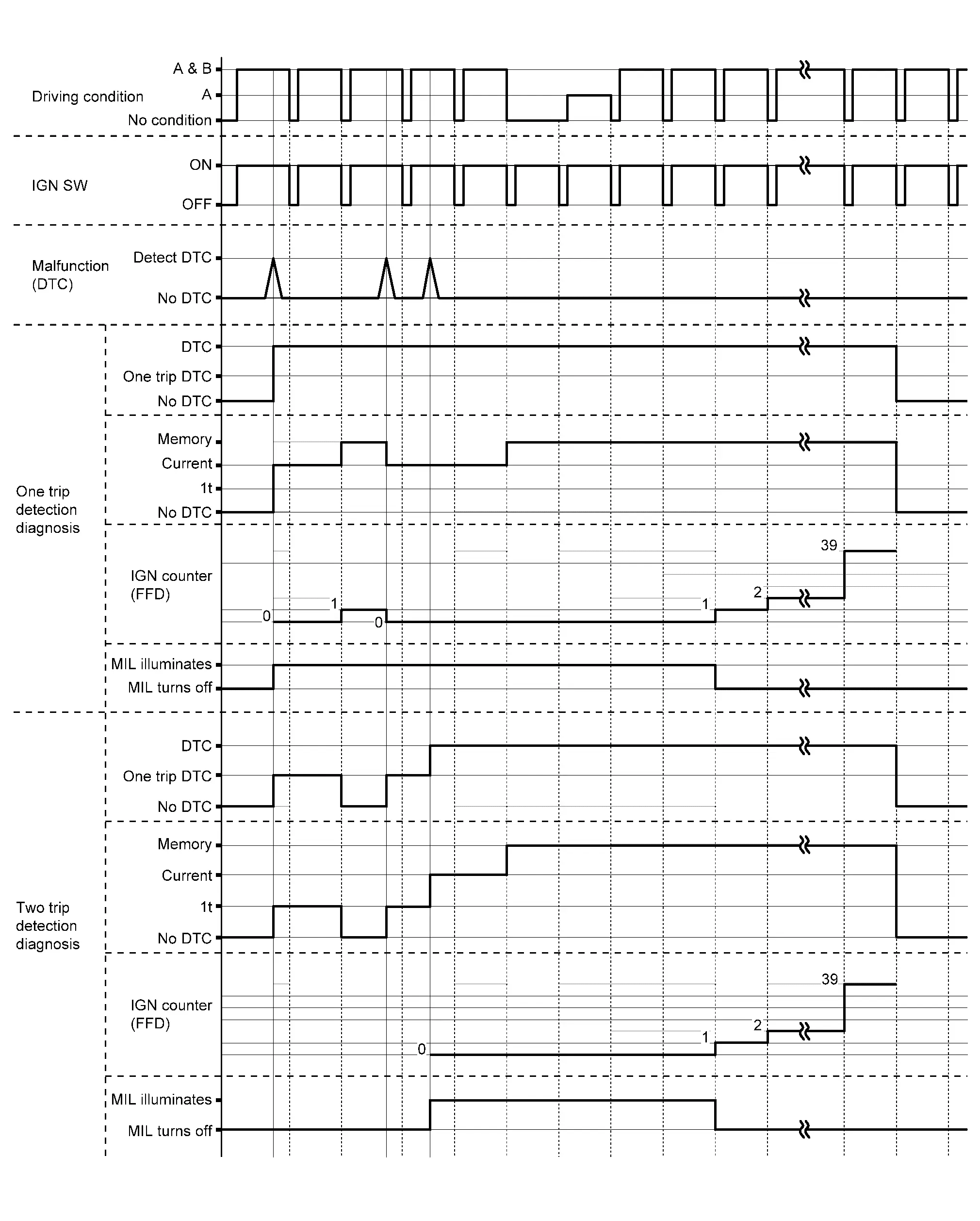
RELATION BETWEEN DTC AT 1ST TRIP/DTC/MIL AND DRIVING CONDITIONS (FOR 2 TRIP DETECTION DIAGNOSIS THAT ILLUMINATES MIL)
-
When initial malfunction is detected, TCM memorizes DTC of the 1st trip. MIL does not light at this stage.
-
If the same malfunction is detected at the 2nd trip, TCM memorizes DTC and MIL lights at the same time.
-
Then, MIL goes off after driving the Nissan Ariya vehicle for 3 trips under ŌĆ£Driving condition BŌĆØ without malfunction.
-
DTC is displayed until 40 trips of ŌĆ£Driving condition AŌĆØ are satisfied with no malfunction on "Driving condition A" after MIL lighting off. DTC is erased when 40 trips are satisfied.
-
When the self-diagnosis result is acceptable at the 2nd trip (conforming to driving condition B), DTC of the 1st trip is erased.
COUNTER SYSTEM LIST
| Item | Driving condition | Trip |
|---|---|---|
| MIL (OFF) | B | 3 |
| DTC (clear) | A | 40 |
| DTC at 1st trip (clear) | B | 1 |
DRIVING CONDITION
Driving condition A
Driving condition A is the driving condition that provides warm-up.
In specific, count-up is performed when all of the following conditions are satisfied.
-
Engine speed is 400 rpm or more.
-
After start of the engine, the water temperature increased by 20┬░C (36┬░F) or more.
-
Water temperature was 70┬░C (158┬░F) or more.
-
The ignition switch was changed from ON to OFF.
NOTE:
-
If the same malfunction is detected regardless of the driving condition, reset the A counter.
-
When the above is satisfied without detecting the same malfunction after turning off MIL, count up the A counter.
-
When MIL goes off due to the malfunction and the A counter reaches 40, the DTC is erased.
Driving condition B
Driving condition B is different by each DTC.
Driving condition of count up for each DTC is as follows;
-
Diagnosis condition* and diagnosis delay time* for each DTC are satisfied.
-
While the above "1" condition is satisfied, threshold* for each DTC is not satisfied.
*: For details of these, refer to DTC/CIRCUIT DIAGNOSIS >> DTC (Pxxxx or Uxxxx) >> DTC Description >> DTC DETECTION LOGIC.
NOTE:
-
If the same malfunction is detected regardless of the driving condition, reset the B counter.
-
When the above is satisfied without detecting the same malfunction, count up the B counter.
-
When the B counter reaches 3 without malfunction, MIL goes off.
-
When the B counter is counted once without detecting the same malfunction after TCM memorizes DTC of the 1st trip, DTC of the 1st trip is erased.
TIME CHART
CONSULT Function
CAUTION:
After disconnecting the CONSULT vehicle interface (VI) from the data link connector, the ignition must be cycled OFF ŌåÆ ON (for at least 5 seconds) ŌåÆ OFF. If this step is not performed, the BCM may not go to ŌĆ£sleep modeŌĆØ, potentially causing a discharged battery and a no-start condition.
APPLICABLE ITEM
| Diagnosis mode | Description |
|---|---|
| Self Diagnostic Result | Display non-network DTC which TCM memorizes |
| Data Monitor | Displays TCM input/output data in real time |
| Work Support | This mode enables a technician to adjust some devices faster and more accurately |
| ECU Identification | Displays TCM part number |
| Replace ECU |
|
SELF DIAGNOSTIC RESULTS
Refer to DTC Index.
When ŌĆ£CRNTŌĆØ is displayed on self-diagnosis result
-
The system is presently malfunctioning.
When ŌĆ£1trip DTCŌĆØ is displayed on self-diagnosis result
-
When malfunction of 1st trip is detected during 2 trip detection diagnosis.
When ŌĆ£PASTŌĆØ is displayed on self-diagnosis result
-
System malfunction in the past is detected, but the system is presently normal.
Freeze Frame Data (FFD)
The following vehicle status is recorded when DTC is detected and is displayed on CONSULT.
| Monitored item | Displayed contents |
|---|---|
| ODO/TRIP METER | Displays the mileage at the time the malfunction is detected. |
| Number of occurrences of fault (Count) |
The DTC counter is displayed in ŌĆ£FFDŌĆØ and the number of times of satisfied ŌĆ£Driving condition AŌĆØ is displayed after normal recovery of DTC. Refer to Counter System.
|
DATA MONITOR
NOTE:
The following table includes information (items) inapplicable to this Nissan Ariya vehicle. For information (items) applicable to this vehicle, refer to CONSULT display items.
| Monitored item | (Unit) | Remarks |
|---|---|---|
| Manual mode signal | Displays the transaxle status of the manual mode signal transmitted through CAN communication. | |
| Gear position | Display the target gear of manual mode. | |
| 2WD/4WD identification | Displays the axle type of the Nissan Ariya vehicle. | |
| Range switch 1 status |
Displays the status of transmission range switch 1 circuit. Normal: Circuit normal Open: Circuit open Low: Intermediate potential (Low) High: Intermediate potential (High) |
|
| Range switch 2 status |
Displays the status of transmission range switch 2 circuit. Normal: Circuit normal Open: Circuit open Low: Intermediate potential (Low) High: Intermediate potential (High) |
|
| Range switch 3 status |
Displays the status of transmission range switch 3 circuit. Normal: Circuit normal Open: Circuit open Low: Intermediate potential (Low) High: Intermediate potential (High) |
|
| Range switch 4 status |
Displays the status of transmission range switch 4 circuit. Normal: Circuit normal Open: Circuit open Low: Intermediate potential (Low) High: Intermediate potential (High) |
|
| Primary speed sensor |
Displays the status of the primary speed sensor circuit. Normal: Circuit normal Open: Circuit open Low: Intermediate potential (Low) High: Intermediate potential (High) |
|
| Secondary speed sensor |
Displays the status of the secondary speed sensor circuit. Normal: Circuit normal Open: Circuit open Low: Intermediate potential (Low) High: Intermediate potential (High) |
|
| Input speed sensor |
Displays the status of the input speed sensor circuit. Normal: Circuit normal Open: Circuit open Low: Intermediate potential (Low) High: Intermediate potential (High) |
|
| Transmission warning indicator DTC | Displays the first DTC when CVT system warning is displayed. | |
| Electric oil pump target speed | Displays the electric oil pump target speed. | |
| Electric oil pump speed | Displays the electric oil pump actual speed. | |
| Idle switch | Displays the reception status of the closed throttle position signal received through CAN communication. | |
| Steering down switch | Displays the operation status of the paddle shifter (down switch). | |
| Steering up switch | Displays the operation status of the paddle shifter (up switch). | |
| CVT lamp |
|
|
| VDC ON | Displays the reception status of the VDC operation signal received through CAN communication. | |
| TCS ON | Displays the reception status of the TCS operation signal received through CAN communication. | |
| ABS fail signal | Displays the reception status of the ABS malfunction signal received through CAN communication. | |
| ABS ON | Displays the reception status of the ABS operation signal received through CAN communication. | |
| G sensor calibration | Displays the status of ŌĆ£G sensor calibrationŌĆØ in ŌĆ£Work SupportŌĆØ. | |
| N idle status |
|
|
| Range switch 1 | Displays the ON/OFF of transmission range switch 1. | |
| Range switch 2 | Displays the ON/OFF of transmission range switch 2. | |
| Range switch 3 | Displays the ON/OFF of transmission range switch 3. | |
| Range switch 4 | Displays the ON/OFF of transmission range switch 4. | |
| Electric oil pump temperature sensor | Displays the temperature sensor status of electric oil pump. | |
| Electric oil pump over current | Displays the over current status of electric oil pump. | |
| Electric oil pump angle sensor | Displays the angle sensor status of electric oil pump. | |
| Electric oil pump low voltage | Displays the low voltage status of electric oil pump. | |
| Electric oil pump temperature status | Displays the over temperature status of electric oil pump. | |
| Electric oil pump signal | Displays the communication signal status of electric oil pump. | |
| Electric oil pump over voltage | Displays the over voltage status of electric oil pump. | |
| Engine brake level | Displays the setting of ŌĆ£ENGINE BRAKE ADJŌĆØ in ŌĆ£Work SupportŌĆØ. | |
| CVT fluid deterioration data | This monitor item do not use. | |
| Torque converter clutch solenoid calibration gain | This monitor item do not use. | |
| Torque converter clutch solenoid calibration offset | This monitor item do not use. | |
| Torque converter clutch solenoid calibration map number | This monitor item do not use. | |
| Torque converter clutch solenoid calibration offset 2 | This monitor item do not use. | |
| Line pressure solenoid calibration gain | This monitor item do not use. | |
| Line pressure solenoid calibration offset | This monitor item do not use. | |
| Line pressure solenoid calibration map number | This monitor item do not use. | |
| Line pressure solenoid calibration offset 2 | This monitor item do not use. | |
| Primary pressure solenoid calibration gain | This monitor item do not use. | |
| Primary pressure solenoid calibration offset | This monitor item do not use. | |
| Primary pressure solenoid calibration map number | This monitor item do not use. | |
| Primary pressure solenoid calibration offset 2 | This monitor item do not use. | |
| Secondary pressure solenoid calibration gain | This monitor item do not use. | |
| Secondary pressure solenoid calibration offset | This monitor item do not use. | |
| Secondary pressure solenoid calibration map number | This monitor item do not use. | |
| Secondary pressure solenoid calibration offset 2 | This monitor item do not use. | |
| Select solenoid calibration gain | This monitor item do not use. | |
| Select solenoid calibration offset | This monitor item do not use. | |
| Select solenoid calibration map number | This monitor item do not use. | |
| Select solenoid calibration offset 2 | This monitor item do not use. | |
| Unit calibration ID1 | This monitor item do not use. | |
| Unit calibration ID2 | This monitor item do not use. | |
| Unit calibration ID3 | This monitor item do not use. | |
| Unit calibration ID4 | This monitor item do not use. | |
| Unit calibration ID5 | This monitor item do not use. | |
| Unit calibration ID6 | This monitor item do not use. | |
| Unit calibration ID7 | This monitor item do not use. | |
| Unit calibration ID8 | This monitor item do not use. | |
| Unit calibration ID9 | This monitor item do not use. | |
| Unit calibration ID10 | This monitor item do not use. | |
| Unit calibration ID11 | This monitor item do not use. | |
| LB - Initialize offset C | This monitor item do not use. | |
| LB - Initialize offset D | This monitor item do not use. | |
| Cancel automatic park function | Displays the ON/OFF of automatic park function cancellation. | |
| LB - Initialize offset E | This monitor item do not use. | |
| LB - Initialize offset F | This monitor item do not use. | |
| Select - Initialize offset E | This monitor item do not use. | |
| Select - Initialize offset F | This monitor item do not use. | |
| H/R - Initialize offset A | This monitor item do not use. | |
| H/R - Initialize offset B | This monitor item do not use. | |
| H/R - Initialize offset C | This monitor item do not use. | |
| H/R - Initialize offset D | This monitor item do not use. | |
| H/R - Initialize offset E | This monitor item do not use. | |
| H/R - Initialize offset F | This monitor item do not use. | |
| LB - Initialize offset A | This monitor item do not use. | |
| LB - Initialize offset B | This monitor item do not use. | |
| Select - Initial learning | This monitor item do not use. | |
| Lock-up - Initial learning | This monitor item do not use. | |
| Select - Initial learning temperature | This monitor item do not use. | |
| Lock-up - Initial learning temperature | This monitor item do not use. | |
| Select (N-D) - Initial learning pressure | This monitor item do not use. | |
| Select (N-D) - Initial learning time | This monitor item do not use. | |
| Select (N-R) - Initial learning pressure | This monitor item do not use. | |
| Select (N-R) - Initial learning time | This monitor item do not use. | |
| Lock-up - Initial learning 1 | This monitor item do not use. | |
| Lock-up - Initial learning 2 | This monitor item do not use. | |
| Select - Initialize offset G | This monitor item do not use. | |
| Nissan Ariya Vehicle speed sensor | (km/h or mph) | Displays the Nissan Ariya vehicle speed calculated from the CVT output shaft speed. |
| Slip revolution | (rpm) | Displays the speed difference between the input shaft speed of CVT and the engine speed. |
| Line pressure | (MPa) | Displays the line pressure calculated from the signal voltage of the line pressure sensor. |
| Line pressure sensor | (V) | Displays the signal voltage of the line pressure sensor. |
| Slip revolution absolute value | (rpm) | This monitor item do not use. |
| Target transmission speed | (sec) | This monitor item do not use. |
| Input speed sensor | (rpm) | Displays the input speed calculated from the pulse signal of the input speed sensor. |
| Primary speed sensor | (rpm) | Displays the primary pulley speed calculated from the pulse signal of the primary speed sensor. |
| Secondary speed sensor | (rpm) | Displays the secondary pulley speed calculated from the pulse signal of the secondary speed sensor. |
| Engine speed signal | (rpm) | Displays the engine speed received through CAN communication. |
| Secondary pressure sensor | (V) | Displays the signal voltage of the secondary pressure sensor. |
| Primary pressure sensor | (V) | Displays the signal voltage of the primary pressure sensor. |
| Transmission fluid temperature sensor | (V) | Displays the signal voltage of the CVT fluid temperature sensor. |
| G sensor | (G) | Displays the signal voltage of the G sensor. |
| Torque ratio | Display the torque ratio of torque converter. | |
| G sensor (TCM) | (V) |
|
| Brake switch | Displays the reception status of the stop lamp switch signal received through CAN communication. | |
| Shift indicator signal | Displays the shift position signal transmitted via CAN communication. | |
| Range | Displays the gear position recognized by TCM. | |
| Estimated Nissan Ariya vehicle speed signal | (km/h or mph) | Displays the Nissan Ariya vehicle speed signal (ABS) received through CAN communication. |
| Ignition power supply voltage | (V) | Displays the battery voltage applied to TCM. |
| Battery power supply voltage | (V) | Displays the backup voltage of TCM. |
| Nissan Ariya Vehicle speed | (km/h or mph) | Displays the Nissan Ariya vehicle speed recognized by TCM. |
| Input speed | (rpm) | Displays the input shaft speed of CVT recognized by TCM. |
| Primary speed | (rpm) | Displays the primary pulley speed recognized by TCM. |
| Secondary speed | (rpm) | Displays the secondary pulley speed recognized by TCM. |
| Engine speed | (rpm) | Displays the engine speed recognized by TCM. |
| Pulley gear ratio | Displays the pulley gear ratio calculated from primary pulley speed/secondary pulley speed. | |
| G speed | (G) | Displays the acceleration and deceleration speed of the Nissan Ariya vehicle calculated from vehicle speed change. |
| Accelerator pedal position | (deg) | Displays the estimated throttle position received through CAN communication. |
| Engine torque | (Nm) | Display the engine torque recognized by TCM. |
| Primary torque | (Nm) | Display the input shaft torque of CVT. |
| Secondary pressure | (MPa) | Displays the secondary pressure calculated from the signal voltage of the secondary pressure sensor. |
| Primary pressure | (MPa) | Displays the primary pressure calculated from the signal voltage of the primary pressure sensor. |
| Transmission fluid temperature | (┬░C or ┬░F) | Displays the CVT fluid temperature calculated from the signal voltage of the CVT fluid temperature sensor. |
| Target pulley speed | (rpm) | Displays the target primary pulley speed calculated from processing of gear shift control. |
| Target gear ratio | Displays the target gear ratio of the pulley from processing of gear shift control. | |
| Target torque converter clutch solenoid differential pressure | (MPa) | Displays the target oil pressure of the torque converter clutch solenoid valve calculated from oil pressure processing of gear shift control. |
| Target line pressure | (MPa) | Displays the target oil pressure of the line pressure solenoid valve calculated from oil pressure processing of gear shift control. |
| Target primary pressure | (MPa) | Displays the target oil pressure of the primary pressure solenoid valve calculated from oil pressure processing of gear shift control. |
| Target select pressure | (MPa) | Displays the target oil pressure of the select solenoid valve calculated from oil pressure processing of gear shift control. |
| Target secondary pressure | (MPa) | Displays the target oil pressure of the secondary pressure solenoid valve calculated from oil pressure processing of gear shift control. |
| Torque converter clutch solenoid current | (mA) | Displays the command current from TCM to the torque converter clutch solenoid valve. |
| Line pressure solenoid current | (mA) | Displays the command current from TCM to the line pressure solenoid valve. |
| Primary pressure solenoid current | (mA) | Displays the command current from TCM to the primary pressure solenoid valve. |
| Secondary pressure solenoid current | (mA) | Displays the command current from TCM to the secondary pressure solenoid valve. |
| Select solenoid current | (mA) | Displays the command current from TCM to the select solenoid valve. |
| Torque converter clutch solenoid current monitor | (mA) | Monitors the command current from TCM to the torque converter clutch solenoid valve and displays the monitored value. |
| Line pressure solenoid current monitor | (mA) | Monitors the command current from TCM to the line pressure solenoid valve and displays the monitored value. |
| Primary pressure solenoid current monitor | (mA) | Monitors the command current from TCM to the primary pressure solenoid valve and displays the monitored value. |
| Secondary pressure solenoid current monitor | (mA) | Monitors the command current from TCM to the secondary pressure solenoid valve and displays the monitored value. |
| Select solenoid current monitor | (mA) | Monitors the command current from TCM to the select solenoid valve and displays the monitored value. |
| G sensor slope | (%) | Displays the gradient angle calculated from the G sensor signal voltage. |
| CVT-B |
|
|
| CVT-A |
|
WORK SUPPORT
| Item name | Description |
|---|---|
| Erase learning value |
|
| Clutch point learning | Allow learning of the forward clutch engagement point. |
| G sensor calibration | Compensates the G sensor. |
| Confirm AT/CVT fluid deterioration | Checks the degradation level of the CVT fluid under severe conditions. |
| Write IP characteristic - Input serial number | Writes IP characteristics when transaxle assembly is replaced. |
| Read IP characteristic - Replacement TCM | Reads IP characteristics when TCM is replaced. |
| Write IP characteristic - Replacement TCM | Writes IP characteristics when TCM is replaced. |
| Engine brake adjustment | Although there is no malfunction on the transaxle and the CVT system, if a customer make a complaint like ŌĆ£I do not feel comfortable with automatic operation of the engine brake on downhillŌĆØ, the engine brake may be cancelled with ŌĆ£engine brake adjustmentŌĆØ. |
| MAC KEY writing | Write MAC key to TCM. |
| Cancel automatic park function | Changes the status of automatic park function cancellation. |
Engine brake adjustment
| ENGINE BRAKE LEVEL | |
| ON | : Turn ON the engine brake control. |
| OFF | : Turn OFF the engine brake control. |
Check the degradation level of the CVT fluid.
| CVTF degradation level data | |
| 210,000 or more | : Replacement of the CVT fluid is required. |
| Less than 210,000 | : Replacement of the CVT fluid is not required. |
Other materials:
Installation d'un dispositif de retenue pour enfant dos ├Ā la route ├Ā l'aide des
ceintures de s├®curit├®
AVERTISSEMENT
Pour votre Nissan Rogue, la ceinture de s├®curit├® ├Ā trois points d'ancrage avec enrouleur ├Ā blocage automatique (ALR) doit imp├®rativement ├¬tre utilis├®e lors de l'installation d'un dispositif de retenue pour enfant. Ne pas utiliser le mode de blocage des enrouleurs (ALR) peut e ...
Dtc/circuit Diagnosis. U2176-87 Can Comm Err (ccm/st Angle Sensor)
DTC Description
DESCRIPTIONCAN (Controller Area Network) is a serial
communication line for real time applications. It is an on-Nissan Ariya
vehicle multiplex communication line with high data communication speed
and excellent error detection ability. Modern Nissan Ariya vehicle is
equipped ...
How to Use This Manual. How to Read Wiring Diagrams
Connector Symbols
Most of connector symbols in wiring diagrams are shown from the terminal side.
Connector symbols shown from the terminal side are enclosed by a single line and followed by the direction mark.
Connector symbols shown from the harness side are enclosed by a double line and ...