Nissan Rogue (T33) 2021-Present Service Manual: Can Gateway :: Ecu Diagnosis Information. Can Gateway
Can Gateway
8ch Can Gateway (8ch Can Gateway)
DTC Index
| DTC | CONSULT display | Reference |
|---|---|---|
| — |
No DTC is detected. Further testing may be required. |
— |
| B2600-42 | Configuration error | DTC Description |
| B2600-46 | Configuration error | DTC Description |
| B2600-49 | Configuration error | DTC Description |
| B2600-56 | Configuration error | DTC Description |
| B2601-42 | Memory failure for firmware over the air | DTC Description |
| B261E-56 | Pairing error | DTC Description |
| B261F-97 | Communication error | DTC Description |
| U1325-54 | Configuration incompletion | DTC Description |
| U2340-87 | CAN communication error (ECM) | DTC Description |
| U2343-87 | CAN communication error (VCM/HCM) | DTC Description |
| U2448-87 | CAN communication error (ABS control unit) | DTC Description |
| U254F-87 | CAN communication error (BCM) | DTC Description |
| U255B-87 | CAN communication error (IPDM E/R) | DTC Description |
| U278C-88 | Ethernet circuit | DTC Description |
| U288C-88 | Ethernet circuit | DTC Description |
| U298C-88 | Ethernet circuit | DTC Description |
| U2A8C-88 | Ethernet circuit | DTC Description |
| U2B8C-88 | Ethernet circuit | DTC Description |
DTC Inspection Priority Chart
If some DTCs are displayed at the same time, perform inspections one by one based on the following priority chart.
| Priority | DTC |
|---|---|
| 1 |
|
| 2 |
|
| 3 |
|
| 4 |
|
| 5 |
|
| 6 |
|
Fail-safe
| DTC | Display contents of CONSULT | Fail-safe condition |
|---|---|---|
| B2600-42 | Configuration error |
The 8CH CAN gateway will stop transmitting and receiving the following:
|
| B2600-46 | Configuration error |
The 8CH CAN gateway will stop transmitting and receiving the following:
|
| B2600-49 | Configuration error |
The 8CH CAN gateway will stop transmitting and receiving the following:
|
| B2600-56 | Configuration error | — |
| B2601-42 | Memory failure for firmware over the air | Software automatic update function (OTA) fails, but system continue normal control. |
| B261E-56 | Pairing error |
|
| B261F-97 | Communication error |
|
| U1325-54 | Configuration incompletion |
The 8CH CAN gateway will stop transmitting and receiving the following:
|
| U2340-87 | CAN communication error (ECM) | System continue normal control. |
| U2343-87 | CAN communication error (VCM/HCM) | System continue normal control. |
| U2448-87 | CAN communication error (ABS control unit) | System continue normal control. |
| U254F-87 | CAN communication error (BCM) | System continue normal control. |
| U255B-87 | CAN communication error (IPDM E/R) | System continue normal control. |
| U278C-88 | Ethernet circuit | 8CH CAN gateway stops transmitting and receiving ethernet communication signals between ethernet communication circuit which cannot communicate. |
| U288C-88 | Ethernet circuit | 8CH CAN gateway stops transmitting and receiving ethernet communication signals between ethernet communication circuit which cannot communicate. |
| U298C-88 | Ethernet circuit | 8CH CAN gateway stops transmitting and receiving ethernet communication signals between ethernet communication circuit which cannot communicate. |
| U2A8C-88 | Ethernet circuit | 8CH CAN gateway stops transmitting and receiving ethernet communication signals between ethernet communication circuit which cannot communicate. |
| U2B8C-88 | Ethernet circuit | 8CH CAN gateway stops transmitting and receiving ethernet communication signals between ethernet communication circuit which cannot communicate. |
Physical Values
With type B meter
TERMINAL LAYOUT
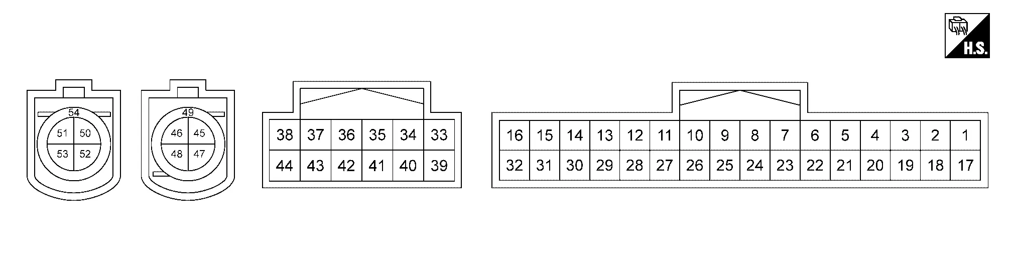
PHYSICAL VALUES
|
Terminal No. (Wire color) | Description | Condition | Standard | Reference value | |||
|---|---|---|---|---|---|---|---|
| + | – | Signal name | Input/ Output | ||||
|
1 (SB)*1 (GR)*2 |
21 (B) 28 (B) |
Battery power supply | Input | Ignition switch OFF | 6 – 16 V | Battery voltage | |
|
2 (LA/W) |
— | Diagnostic CAN communication-L | Input/ Output | — | — | — | |
|
3 (LA/L) |
— | Diagnostic CAN communication-H | Input/ Output | — | — | — | |
|
4 (LA/W) |
— | Diagnostic CAN communication-L | Input/ Output | — | — | — | |
|
5 (LA/L) |
— | Diagnostic CAN communication-H | Input/ Output | — | — | — | |
|
6 (R) |
— | Drivetrain CAN communication 2-L | Input/ Output | — | — | — | |
|
7 (GR) |
— | Drivetrain CAN communication 2-H | Input/ Output | — | — | — | |
|
10 (G) |
— | Chassis CAN communication 4-L | Input/ Output | — | — | — | |
|
11 (GR) |
— | Chassis CAN communication 4-H | Input/ Output | — | — | — | |
|
17 (LA/Y)*1 (Y)*2 |
21 (B) 28 (B) |
Ignition switch ON power supply | Input | Ignition switch ON | 7 – 16 V | Battery voltage | |
|
19 (LA/SB) |
— | IT CAN communication-H | Input/ Output | — | — | — | |
|
20 (LA/V) |
— | IT CAN communication-L | Input/ Output | — | — | — | |
|
21 (B) |
Ground | Ground | — | Ignition switch ON | — | Approx. 0 V | |
|
22 (LA/SB) |
— | IT CAN communication-H | Input/ Output | — | — | — | |
|
23 (LA/V) |
— | IT CAN communication-L | Input/ Output | — | — | — | |
|
28 (B) |
Ground | Ground | — | Ignition switch ON | — | Approx. 0 V | |
|
33 (L) |
— | Nissan Ariya Vehicle CAN communication 4-H | Input/ Output | — | — | — | |
|
34 (P) |
— | Nissan Ariya Vehicle CAN communication 4-L | Input/ Output | — | — | — | |
|
37 (BR) |
— | ITS CAN communication 4-H | Input/ Output | — | — | — | |
|
38 (W) |
— | ITS CAN communication 4-L | Input/ Output | — | — | — | |
|
43 (P) |
— | ITS CAN communication 1-L | Input/ Output | — | — | — | |
|
44 (BR) |
— | ITS CAN communication 1-H | Input/ Output | — | — | — | |
|
47 (G) |
— | Ethernet (-) | — | — | — | — | |
|
48 (Y) |
— | Ethernet (+) | — | — | — | — | |
|
49 (Shield) |
— | Shield | — | — | — | — | |
|
52 (G) |
— | Ethernet (-) | — | — | — | — | |
|
53 (Y) |
— | Ethernet (+) | — | — | — | — | |
|
54 (Shield) |
— | Shield | — | — | — | — | |
*1: JPAN production
*2: USA production
With type A meter
TERMINAL LAYOUT
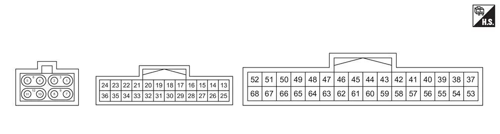
PHYSICAL VALUES
|
Terminal No. (Wire color) | Description | Condition | Standard | Reference value | |||
|---|---|---|---|---|---|---|---|
| + | – | Signal name | Input/ Output | ||||
|
1 (G) |
— | Ethernet (-) | — | — | — | — | |
|
2 (Y) |
— | Ethernet (+) | — | — | — | — | |
|
3 (Shield) |
— | Shield | — | — | — | — | |
|
4 (G) |
— | Ethernet (-) | — | — | — | — | |
|
5 (Y) |
— | Ethernet (+) | — | — | — | — | |
|
6 (Shield) |
— | Shield | — | — | — | — | |
|
7 (G) |
— | Ethernet (+) | — | — | — | — | |
|
8 (Y) |
— | Ethernet (-) | — | — | — | — | |
|
9 (Shield) |
— | Shield | — | — | — | — | |
|
10 (G) |
— | Ethernet (+) | — | — | — | — | |
|
11 (Y) |
— | Ethernet (-) | — | — | — | — | |
|
12 (Shield) |
— | Shield | — | — | — | — | |
|
15 (LA/SB) |
— | IT CAN communication 2-H | Input/ Output | — | — | — | |
|
16 (LA/R) |
— | IT CAN communication 2-L | Input/ Output | — | — | — | |
|
17 (BR) |
— | ITS CAN communication 4-H | Input/ Output | — | — | — | |
|
18 (W) |
— | ITS CAN communication 4-L | Input/ Output | — | — | — | |
|
21 (LA/Y) |
— | — | — | — | — | — | |
|
22 (LA/SB) |
— | — | — | — | — | — | |
|
23 (P) |
— | ITS CAN communication 1-L | Input/ Output | — | — | — | |
|
24 (BR) |
— | ITS CAN communication 1-H | Input/ Output | — | — | — | |
|
25 (LA/SB) |
— | IT CAN communication 1-H | Input/ Output | — | — | — | |
|
26 (LA/V) |
— | IT CAN communication 1-L | Input/ Output | — | — | — | |
|
27 (LA/SB) |
— | IT CAN communication 2-H | Input/ Output | — | — | — | |
|
28 (LA/R) |
IT CAN communication 2-L | Input/ Output | — | — | |||
|
37 (GB)*1 (SB)*2 |
57 (B) 64 (B) |
Battery power supply | Input | Ignition switch OFF | 6 – 16 V | Battery voltage | |
|
38 (LA/W) |
— | Diagnostic CAN communication-L | Input/ Output | — | — | — | |
|
39 (LA/L) |
— | Diagnostic CAN communication-H | Input/ Output | — | — | — | |
|
40 (LA/W) |
— | Diagnostic CAN communication-L | Input/ Output | — | — | — | |
|
41 (LA/L) |
— | Diagnostic CAN communication-H | Input/ Output | — | — | — | |
|
42 (R) |
— | Drivetrain CAN communication 2-L | Input/ Output | — | — | — | |
|
43 (GR) |
— | Drivetrain CAN communication 2-H | Input/ Output | — | — | — | |
|
44 (LA/W) |
— | IT CAN communication 3-L | Input/ Output | — | — | — | |
|
45 (LA/SW) |
— | IT CAN communication 3-H | Input/ Output | — | — | — | |
|
46 (P) |
— | Nissan Ariya Vehicle CAN communication 4-L | Input/ Output | — | — | — | |
|
47 (L) |
— | Nissan Ariya Vehicle CAN communication 4-H | Input/ Output | — | — | — | |
|
51 (P) |
— | — | — | — | — | — | |
|
52 (V) |
— | — | — | — | — | — | |
|
53 (LA/Y)*1 (Y)*2 |
57 (B) 64 (B) |
Ignition switch ON power supply | Input | Ingition switch ON | 7 – 16 V | Battery voltage | |
|
55 (LA/SB) |
— | IT CAN communication 1-H | Input/ Output | — | — | — | |
|
56 (LA/V) |
— | IT CAN communication 1-L | Input/ Output | — | — | — | |
|
57 (B) |
Ground | Ground | — | Ignition switch ON | — | Approx. 0 V | |
|
58 (LA/SB) |
— | IT CAN communication 3-H | Input/ Output | — | — | — | |
|
59 (LA/W) |
— | IT CAN communication 3-L | Input/ Output | — | — | — | |
|
60 (GR) |
— | Chassis CAN communication 6-H | Input/ Output | — | — | — | |
|
61 (P) |
— | Chassis CAN communication 6-L | Input/ Output | — | — | — | |
|
62 (GR) |
— | Chassis CAN communication 4-H | Input/ Output | — | — | — | |
|
63 (G) |
— | Chassis CAN communication 4-L | Input/ Output | — | — | — | |
|
64 (B) |
Ground | Ground | — | Ignition switch ON | — | Approx. 0 V | |
|
66 (BG) |
— | — | — | — | — | — | |
|
67 (LG) |
— | — | — | — | — | — | |
|
68 (R) |
— | — | — | — | — | — | |
*1: JPAN production
*2: USA production
Other materials:
Dtc/circuit Diagnosis. Front Washer Circuit
Component Function Check
CHECK FRONT WASHER OPERATION
When the front washer switch is turned to the ON position the front washer should operate.
Is front washer operation normal?
YES>>
Washer switch circuit is normal.
NO>>
Refer to Diagnosis Procedure.
Diagnosis Procedure
COMB ...
Symptom Diagnosis. Engine Can Not Start
Description
Engine does not start when push-button ignition switch is pressed.SYMPTOM TABLE (BOTH INTELLIGENT KEYS HAVE THE SAME SYMPTOMS) Door lock operation (remote keyless entry)
Door lock operation (request switch of front/rear/back door) or
trunk/back door open operation (opener switch of ...
Component Parts
Engine Control System
Component Parts Location
ENGINE ROOM COMPARTMENT
Right front of Nissan Ariya vehicle
Left front of vehicle
Nissan Ariya Vehicle front
IPDM E/R
ECM
Admission valve
Turbocharger boost senso ...