Nissan Rogue Service Manual: C1197 vacuum sensor
DTC Logic
DTC DETECTION LOGIC
| DTC | Display Item | Malfunction detected condition | Possible causes |
| C1197 | VACUUM SENSOR | When a malfunction is detected in vacuum sensor. |
|
DTC CONFIRMATION PROCEDURE
1.CHECK SELF-DIAGNOSTIC RESULT
 With CONSULT.
- Turn the ignition switch ON.
- Perform self-diagnostic result.
Is DTC C1197 detected? YES >> Proceed to diagnosis procedure. Refer to BRC-105, "Diagnosis Procedure".
NO >> Inspection End.
Diagnosis Procedure
Regarding Wiring Diagram information, refer to BRC-57, "Wiring Diagram".
1.CHECK BRAKE BOOSTER
- Turn the ignition switch OFF.
- Check brake booster. Refer to BR-10, "Inspection".
Is the inspection result normal? YES >> GO TO 2.
NO >> Replace brake booster. Refer to BR-30, "Removal and installation".
2.CHECK VACUUM PIPING
Check vacuum piping. Refer to BR-32, "Exploded View".
Is the inspection result normal? YES >> GO TO 3.
NO >> Replace vacuum piping. Refer to BR-32, "Removal and Installation".
3.CHECK VACUUM SENSOR CIRCUIT
- Disconnect vacuum sensor harness connector.
- Disconnect ABS actuator and electric unit (control unit) harness connector.
- Check continuity between vacuum sensor harness connector and ABS actuator and electric unit (control unit) harness connector.
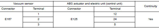
- Check continuity between vacuum sensor harness connector and ground.
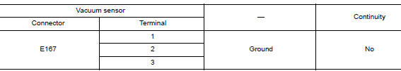
Is the inspection result normal? YES >> GO TO 4.
NO >> Repair or replace malfunctioning components.
4.CHECK TERMINAL
- Check vacuum sensor pin terminals for damage or loose connection with harness connector.
- Check ABS actuator and electric unit (control unit) pin terminals for damage or loose connection with harness connector.
Is the inspection result normal? YES >> GO TO 5.
NO >> Repair or replace malfunctioning components.
5.REPLACE VACUUM SENSOR
 With CONSULT
- Connect ABS actuator and electric unit (control unit) harness connector.
- Replace vacuum sensor. Refer to BR-30, "Exploded View".
CAUTION: Always replace brake booster because vacuum sensor cannot be disassembled.
- Erase self-diagnosis result for ŌĆ£ABSŌĆØ.
- Turn the ignition switch OFF.
- Start engine.
- Perform self-diagnosis for ŌĆ£ABSŌĆØ.
Is DTC ŌĆ£C1197ŌĆØ detected? YES >> Replace ABS actuator and electric unit (control unit). Refer to BRC-136, "Removal and Installation".
NO >> Inspection End.
 C1170 variant coding
DTC Logic
DTC DETECTION LOGIC
DTC
Display Item
Malfunction detected condition
Possible causes
C1170
VARIANT CODING
When the information in ABS actuator and electric
...
 C1198 vacuum sensor
DTC Logic
DTC DETECTION LOGIC
DTC
Display Item
Malfunction detected condition
Possible causes
C1198
VACUUM SEN CIR
When an open circuit is detected in vacuum ...
Other materials:
Charging system preliminary inspection
Diagnosis Procedure
1.CHECK BATTERY TERMINALS CONNECTION
Check if battery terminals are clean and tight.
Is the inspection result normal?
YES >> GO TO 2.
NO >> Repair battery terminal connection. Confirm repair by performing complete
Charging system test
using EXP-800 NI or G ...
Vehicle recovery (freeing a stuck vehicle)
FRONT
Securely install the vehicle recovery hook stored with jacking tools.
Check that the hook is properly secured in the stored place after use.
WARNING:
Stand clear of a stuck vehicle.
Never spin your tires at high speed. This could cause them to
explode and result in ser ...
Precaution
Precaution for Supplemental Restraint System (SRS) "AIR BAG" and "SEAT
BELT
PRE-TENSIONER"
The Supplemental Restraint System such as ŌĆ£AIR BAGŌĆØ and ŌĆ£SEAT BELT
PRE-TENSIONERŌĆØ, used along
with a front seat belt, helps to reduce the risk or severity of injury to the
...
