Nissan Rogue Service Manual: C1198 vacuum sensor
DTC Logic
DTC DETECTION LOGIC
| DTC | Display Item | Malfunction detected condition | Possible causes |
| C1198 | VACUUM SEN CIR |
|
|
DTC CONFIRMATION PROCEDURE
1.CHECK SELF-DIAGNOSTIC RESULT
 With CONSULT.
- Turn the ignition switch ON.
- Perform self-diagnostic result.
Is DTC C1198 detected? YES >> Proceed to diagnosis procedure. Refer to BRC-107, "Diagnosis Procedure".
NO >> Inspection End.
Diagnosis Procedure
Regarding Wiring Diagram information, refer to BRC-57, "Wiring Diagram".
1.CHECK VACUUM SENSOR CIRCUIT
- Turn the ignition switch OFF.
- Disconnect vacuum sensor harness connector.
- Disconnect ABS actuator and electric unit (control unit) harness connector.
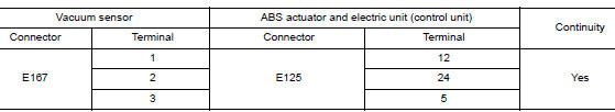
- Check continuity between vacuum sensor harness connector and ABS actuator and electric unit (control unit) harness connector.
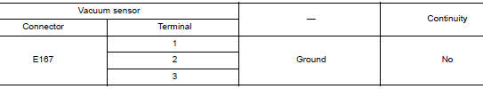
- Check continuity between vacuum sensor harness connector and ground.
Is the inspection result normal? YES >> GO TO 2.
NO >> Repair or replace malfunctioning components.
2.CHECK TERMINAL
- Check vacuum sensor pin terminals for damage or loose connection with harness connector.
- Check ABS actuator and electric unit (control unit) pin terminals for damage or loose connection with harness connector.
Is the inspection result normal? YES >> GO TO 3.
NO >> Repair or replace malfunctioning components.
3.REPLACE VACUUM SENSOR
With CONSULT
- Connect ABS actuator and electric unit (control unit) harness connector.
- Replace vacuum sensor. Refer to BR-30, "Exploded View".
CAUTION: Always replace brake booster because vacuum sensor cannot be disassembled.
- Erase self-diagnosis result for “ABS”.
- Turn the ignition switch OFF.
- Start engine.
- Perform self-diagnosis for “ABS”.
Is DTC “C1198” detected? YES >> Replace ABS actuator and electric unit (control unit). Refer to BRC-136, "Removal and Installation".
NO >> Inspection End.
 C1197 vacuum sensor
DTC Logic
DTC DETECTION LOGIC
DTC
Display Item
Malfunction detected condition
Possible causes
C1197
VACUUM SENSOR
When a malfunction is detected in vacuum sensor.
...
 C1199 brake booster
DTC Logic
DTC DETECTION LOGIC
DTC
Display Item
Malfunction detected condition
Possible causes
C1199
BRAKE BOOSTER
When brake booster vacuum is approx. 0 kPa (0 mm-
...
Other materials:
Instrument lower panel LH
Removal and Installation
REMOVAL
Release instrument side finisher (LH) (1) pawls using a suitable
tool and remove.
: Pawl
Remove bolts (A) and fuel filler lid/hood lock release handle (1)
from instrument lower panel LH.
Remove data link cover from the instrument lowe ...
Front wiper drive assembly
Exploded View
REMOVAL
Cowl top
Front wiper drive assembly
Removal and Installation
REMOVAL
Remove cowl top cover. Refer to EXT-25, "Removal and
Installation".
Disconnect harness connector from front wiper motor.
Remove bolts and front wiper driv ...
Component parts
METER SYSTEM
METER SYSTEM : Component Parts Location
Vehicle front
View of the fuel pump and fuel level
sensor inspection hole covers with
the rear seat removed.
View of front engine assembly
No.
Component
Function
1
Combination me ...
