Nissan Rogue Service Manual: Component parts
METER SYSTEM
METER SYSTEM : Component Parts Location
 Vehicle front
- View of the fuel pump and fuel level sensor inspection hole covers with the rear seat removed.
- View of front engine assembly
|
No. |
Component |
Function |
| 1 | Combination meter | Refer to MWI-8, "METER SYSTEM : System Description". |
| 2 | Steering switch | Refer to MWI-18, "Switch Name and Function". |
| 3 | Meter control switch | Refer to MWI-18, "Switch Name and Function". |
| 4 | Fuel level sensor unit (sub) | Transmits the fuel level sensor signal to the combination meter. |
| 5 | Fuel level sensor unit (main) | Transmits the fuel level sensor signal to the combination meter |
| 6 | Seat belt buckle switch LH | Transmits the seat belt buckle switch signal LH to the combination meter. |
| 7 | ABS actuator and electric unit (control unit) |
|
| 8 | Engine oil pressure sensor | Transmits the engine oil pressure sensor signal to the ECM. |
| 9 | Washer fluid level switch |
|
| 10 | Ambient sensor |
|
| 11 | ECM |
|
| 12 | TCM |
|
| 13 | BCM |
|
| 14 | Parking brake switch | Transmits the parking brake switch signal to the combination meter. |
METER SYSTEM : Design
ARRANGEMENT OF COMBINATION METER
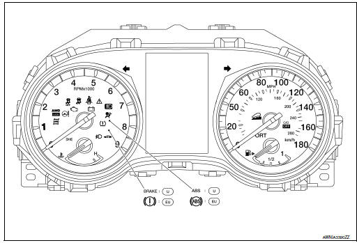
U: USA
EU: Except USA

 System
METER SYSTEM
METER SYSTEM : System Description
SYSTEM DIAGRAM
Combination Meter Input Signal (CAN Communication Signal)
DESCRIPTION
Combination Meter
The combination meter c ...
Other materials:
Thermostat and water control
valve
Exploded View
Water inlet
Thermostat
Rubber ring
To radiator hose (lower)
NOTE:
When removing components such as hoses, tubes/lines, etc., cap or plug openings
to prevent fluid from spilling.
Removal and Installation
WARNING:
Do not remove the radiator ...
How to switch the display
With the ignition switch in the ON position, press
the CAMERA button or move the shift lever to the
R (Reverse) position to operate the Around View
Monitor.
The Around View Monitor displays different split
screen views depending on the position of the
shift lever. Press the CAMERA button to ...
Unit disassembly and assembly
FRONT DRIVE SHAFT
Exploded View (LH)
Shaft
Circular clip
Dust shield
Housing
Snap ring
Spider assembly
Stopper ring
Boot
Boot band
Joint sub-assembly
Wheel side
Disassembly and Assembly (LH)
DISASSEMBLY
Transaxle Assembly Side
Fix shaft ...
