Nissan Rogue Service Manual: Thermostat and water control valve
Exploded View
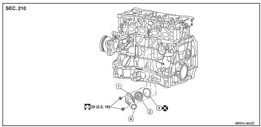
- Water inlet
- Thermostat
- Rubber ring
- To radiator hose (lower)
NOTE: When removing components such as hoses, tubes/lines, etc., cap or plug openings to prevent fluid from spilling.
Removal and Installation
WARNING: Do not remove the radiator cap when the engine is hot. Serious burns could occur from high-pressure engine coolant escaping from the radiator. Wrap a thick cloth around the cap. Slowly push down and turn it a quarter turn to allow built-up pressure to escape. Carefully remove the cap by pushing it down and turning it all the way.
REMOVAL
- Drain engine coolant from the radiator. Refer to CO-8, "Draining".
CAUTION:
- Perform this step when the engine is cold.
- Do not spill coolant on drive belt.
- Remove engine under cover. Refer to EXT-37, "ENGINE UNDER COVER : Removal and Installation".
- Remove radiator hose (lower) from the water inlet side.
- Remove exhaust manifold heat shield. Refer to EM-29, "Exploded View".
- Remove water inlet and thermostat.
INSTALLATION
Installation is in the reverse order of removal.
- Install the thermostat with the whole circumference of the flange fitting securely inside the rubber ring.
CAUTION:
- Do not reuse rubber ring.
- Ensure thermostat rubber ring mounting surface is free from dents or flaws.
- Install the thermostat with the jiggle valve facing upwards. The position deviation may be within the range of ±20°.
- After installation, refill coolant and check for leaks. Refer to CO-9, "Refilling" and CO-8, "Inspection".
Inspection
INSPECTION AFTER REMOVAL
- Place a thread (A) so that it is caught in the valves of thermostat (1) and water control valve. Immerse fully in a container (B) filled with water. Heat while stirring. (The example in the figure shows thermostat.)
- The valve opening temperature is the temperature at which the valve opens and falls from the thread.
- Continue heating. Check the maximum valve lift amount.
NOTE: The maximum valve lift amount standard temperature for water control valve is the reference value.
- After checking the maximum valve lift amount, lower the water temperature and check the valve closing temperature
Standard Thermostat : Refer to CO-25, "Thermostat".
- If out of the standard, replace either or both thermostat and water control valve.
INSPECTION AFTER INSTALLATION
- Check for leakage of engine coolant using the radiator cap tester adapter (commercial service tool) and the radiator cap tester (commercial service tool). Refer to CO-8, "Inspection".
- Start and warm up engine. Check visually that there is no leakage of engine coolant.
 Water pump
Exploded View
Cylinder block
Water pump
Water pump gasket
Water pump housing
O-ring
Water pipe
Water pump housing gasket
Refer to INSTALLAT ...
 Water outlet and water piping
Exploded View
Water outlet
Water temperature sensor
Water outlet O-ring
Clamp
Heater pipe O-ring
Heater pipe
Water hose
Refer to INSTALLATION
Remova ...
Other materials:
Troubleshooting guide
Verify the location of all Intelligent Keys that are
programmed for the vehicle. If another Intelligent
Key is in range or inside the vehicle, the vehicle
system may respond differently than expected.
Symptom
Possible Cause
Remedy
When stopping the engine
The Shift to Pa ...
C1770, C1771, C1772, C1773 G sensor
DTC Description
DTC DETECTION LOGIC
DTC
Display Item
Malfunction Detected Condition
Possible Causes
C1770
G SENSOR FL
(G sensor front left)
Malfunction in the G sensor data from front left wheel sensor.
Tire pressure sensor
Tire pressure rece ...
Combination meter
Reference Value
VALUES ON THE DIAGNOSIS TOOL
*: DDS (hill descent control)
NOTE:
Some items are not available according to vehicle specification.
TERMINAL LAYOUT
PHYSICAL VALUES
Fail-safe
The combination meter activates the fail-safe control if the CAN
communica ...
