Nissan Rogue Service Manual: System
METER SYSTEM
METER SYSTEM : System Description
SYSTEM DIAGRAM
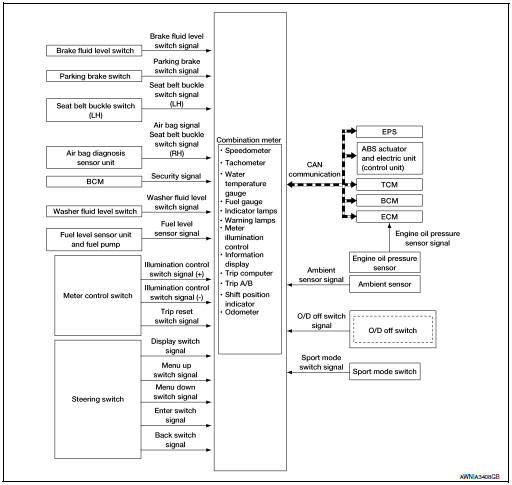
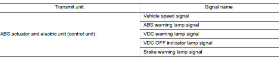
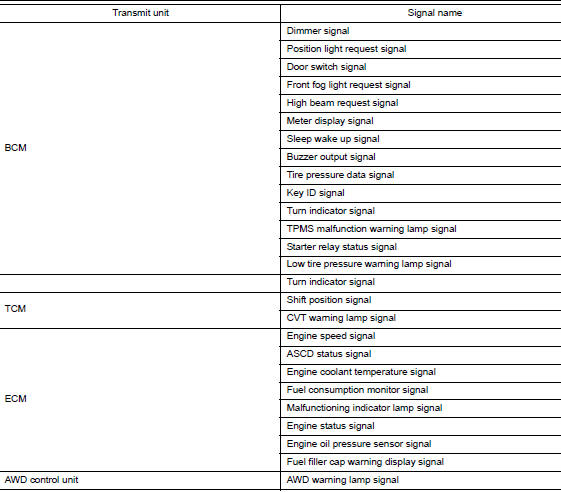
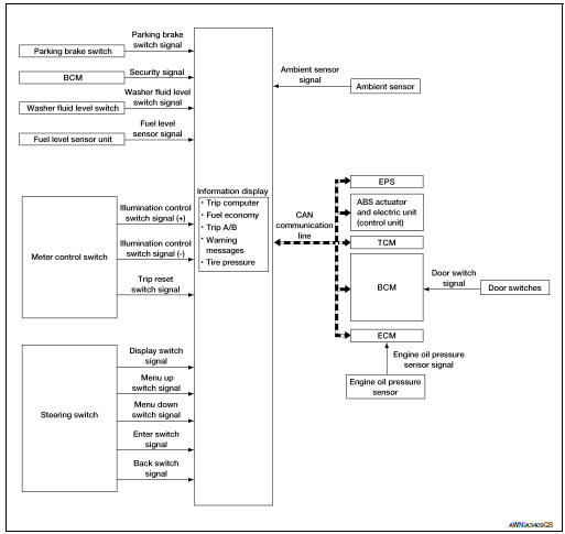
Combination Meter Input Signal (CAN Communication Signal)
DESCRIPTION
Combination Meter
- The combination meter controls the following items according to the signals received from each unit via CAN communication and the signals from switches and sensors.
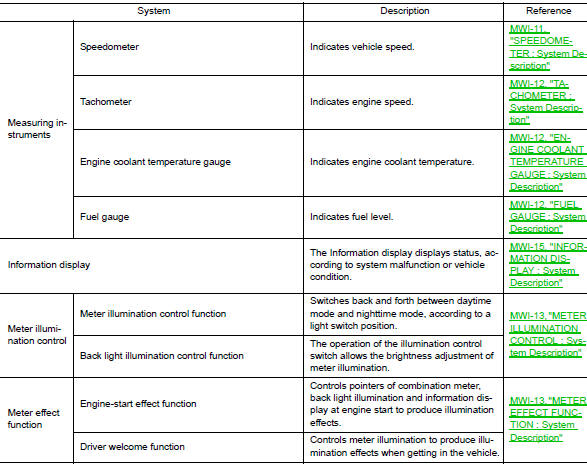
- Measuring instruments
- Speedometer
- Tachometer
- Engine coolant temperature gauge
- Fuel gauge
- Warning lamps
- Indicator lamps
- Meter illumination control
- Meter effect function
- Information display
- The combination meter incorporates a buzzer function that sounds an audible alarm with the integrated buzzer. Refer to WCS-6, "WARNING CHIME SYSTEM : System Description" for further details.
- The combination meter includes an on board diagnosis function.
- The combination meter can be diagnosed with CONSULT.
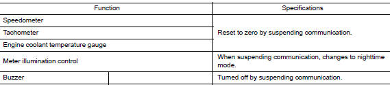
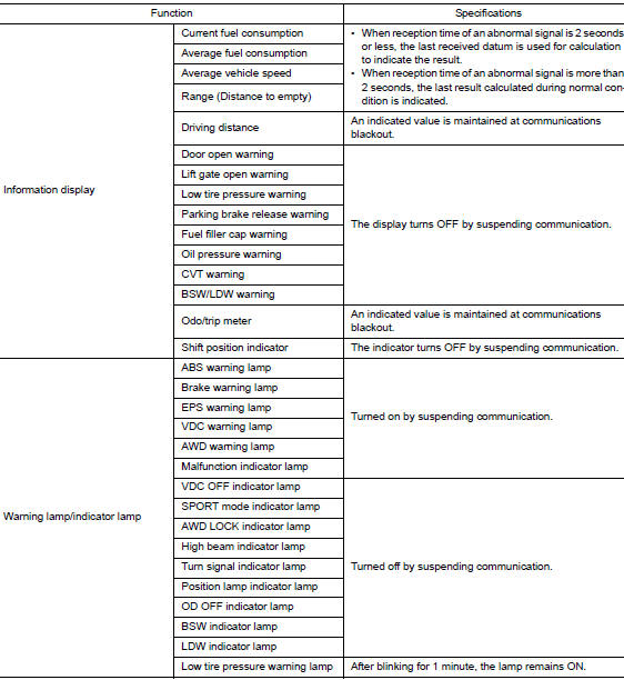
METER CONTROL FUNCTION LIST
METER SYSTEM : Fail-safe
The combination meter activates the fail-safe control if the CAN communication lines between each unit are malfunctioning.
SPEEDOMETER
SPEEDOMETER : System Description
SYSTEM DIAGRAM
DESCRIPTION
The ABS actuator and electric unit (control unit) receives each wheel speed sensor signal and provides a vehicle speed signal to the combination meter via CAN communication lines.
TACHOMETER
TACHOMETER : System Description
SYSTEM DIAGRAM
DESCRIPTION
The crank position sensor sends a crankshaft position signal to the ECM. The ECM provides an engine speed signal to the combination meter via CAN communication lines. The tachometer indicates engine speed in revolutions per minute (rpm).
ENGINE COOLANT TEMPERATURE GAUGE
ENGINE COOLANT TEMPERATURE GAUGE : System Description
SYSTEM DIAGRAM
DESCRIPTION
The engine coolant temperature sensor sends an engine coolant temperature signal to the ECM. The ECMprovides an engine coolant temperature signal to the combination meter via CAN communication lines. The engine coolant temperature gauge indicates the engine coolant temperature.
FUEL GAUGE
FUEL GAUGE : System Description
SYSTEM DIAGRAM
DESCRIPTION
The fuel level sensor unit sends a variable resistor signal to the combination meter. The fuel gauge indicates the approximate fuel level in the fuel tank.
METER ILLUMINATION CONTROL
METER ILLUMINATION CONTROL : System Description
SYSTEM DIAGRAM
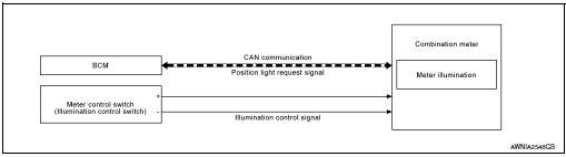
DESCRIPTION
Meter Illumination Control Function
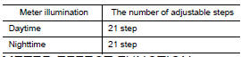
The operation of the illumination control switch changes brightness of the meter illumination.
METER EFFECT FUNCTION
METER EFFECT FUNCTION : System Description
SYSTEM DIAGRAM
ENGINE-START EFFECT FUNCTION
When recognizing an engine start, the combination meter controls the following items for producing the effect:
- Speedometer
- Tachometer
- Engine coolant temperature gauge
- Fuel gauge
- Meter illumination
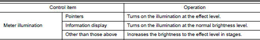
Meter and Illumination Operations During Engine-start Effect
The combination meter controls the following items during the engine-start effect.
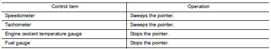
NOTE: The pointers are stopped and illumination is turned off while cranking the engine.
Engine Start Judgement
The combination meter judges “engine-start” and activates the engine-start effect only once when the following operational conditions are all satisfied.
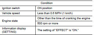
NOTE: Engine-start effect exits when any of the above operational conditions is cancelled during the engine-start effect.
INFORMATION DISPLAY
INFORMATION DISPLAY : System Description
SYSTEM DIAGRAM
FUNCTION
The information display can indicate the following items:
- Outside air temperature
- Trip computer
- Intelligent Key operation information
- CVT shift position indicator
- Odometer
- Warning/Indication messages (door open, lift gate open, low oil pressure, CVT, AWD, I-Key, low fuel, low washer fluid, release parking brake, low tire pressure and loose fuel cap).
OUTSIDE AIR TEMPERATURE INDICATION
The combination meter receives the ambient sensor signal and displays the ambient temperature in the information display.
LOOSE FUEL CAP MESSAGE
The LOOSE FUEL CAP message will display in the information display when the fuel-filler cap is not tightened correctly. The message will turn off as soon as the ECM detects the fuel-filler cap is properly tightened. The ECM provides a loose fuel cap signal to the combination meter via CAN communication lines.
LOW TIRE PRESSURE WARNING
This warning appears when the BCM detects low inflation pressure or a system malfunction. The BCM sends a signal to the combination meter via CAN communication to illuminate the low tire pressure warning lamp. In addition, a warning message will be displayed in the vehicle information display.
DOOR OPEN WARNING
This warning appears when the ignition switch is ON and the door is open. The BCM receives a door switch signal from the door open door switch. The BCM sends the door switch signal to the combination meter via CAN communication lines.
LIFTGATE OPEN WARNING
This warning appears when the ignition switch is ON and the liftgate is opened. The BCM receives a back door switch signal from the back door switch. The BCM sends the door switch signal to the combination meter via CAN communication lines.
LOW FUEL WARNING
This warning appears when the fuel level in the fuel tank is low.
LOW WINDSHIELD WASHER FLUID WARNING
When the windshield washer fluid level is low, the washer fluid level switch provides a ground signal to the combination meter and the warning is displayed. Once fluid is added, the switch opens and the warning is no longer displayed.
RELEASE PARKING BRAKE WARNING
When the parking brake is applied, the parking brake switch provides a ground signal to the combination meter. When the vehicle speed is greater than 4 MPH (7 km/h), the message is displayed and the warning chime sounds.
SHIFT POSITION INDICATOR
The combination meter activates the shift position indicator and manual mode information based on signals received from TCM via CAN communication.
LOW OIL PRESSURE WARNING
The low oil pressure warning appears in the information display when the combination meter receives a low engine oil pressure signal from the ECM via CAN communication
WARNING CHECK INDICATION
The combination meter can cause an interrupt on the information display to indicate a warning, based on signals received from each unit and switch.
Refer to Owner’s Manual for additional information display items.
COMPASS
COMPASS : Description
DESCRIPTION
With the ignition switch in the ON position, and the mode or (N) switch ON, the compass display will indicate the direction the vehicle is heading.
Vehicle direction is displayed as follows:
- N: north
- E: east
- S: south
- W: west
ZONE VARIATION SETTING PROCEDUR
The difference between magnetic north and geographical north can sometimes be great enough to cause false compass readings. This difference is known as variance. In order for the compass to operate properly (accurately) in a particular zone, the zone variation must be calibrated using the following procedure.
Zone Variation Chart
- Determine your location on the zone map.
- Turn the ignition switch to the ON position.
- Press and hold the (N) switch for about 5 seconds. The current zone number will appear in the display.
- Press the mode or (N) switch repeatedly until the desired zone number appears in the display.
Once the desired zone number is displayed, stop pressing the mode or (N) switch and the display will show a compass direction after a few seconds.
NOTE: Use zone number 5 for Hawaii.
CALIBRATION PROCEDURE
The compass display is equipped with an automatic correction function. If the compass display reads “CAL” or the direction is not shown correctly, perform the correction procedure below.
- Press and hold the (N) switch for about 10 seconds. The display will read “CAL”.
- Drive the vehicle slowly in a circle, in an open, safe place. The
initial calibration is completed in about 3 turns.
NOTE: In places where the terrestrial magnetism is extremely disturbed, the initial correction may start automatically.
 Component parts
METER SYSTEM
METER SYSTEM : Component Parts Location
Vehicle front
View of the fuel pump and fuel level
sensor inspection hole covers with
the rear seat removed.
View of f ...
 Operation
Switch Name and Function
STEERING SWITCH
No.
Switch name
Operation
Description
1
Enter/Up/Down switch
Press
The information display settings can be changed.
...
Other materials:
Diagnosis system (BCM) (without intelligent key system)
COMMON ITEM
COMMON ITEM : CONSULT Function (BCM - COMMON ITEM)
APPLICATION ITEM
CONSULT performs the following functions via CAN communication with BCM.
Direct Diagnostic Mode
Description
Ecu Identification
The BCM part number is displayed.
Self Diagnostic ...
Fuel level sensor signal circuit
Component Function Check
1.COMBINATION METER INPUT SIGNAL
Select "METER/M&A" on "CONSULT".
Using "FUEL METER" of "Data Monitor", compare the value of "Data
Monitor" with fuel gauge pointer of
combination meter.
Does ...
Removal and installation
ACCELERATOR PEDAL ASSEMBLY
Exploded View
Brake pedal
Accelerator pedal assembly
Locator hook
Locator pin
Bolt
Removal and Installation
REMOVAL
Disconnect the harness connector from the accelerator pedal
assembly.
Remove the bolts, then rem ...
