Nissan Rogue Service Manual: Removal and installation
ACCELERATOR PEDAL ASSEMBLY
Exploded View
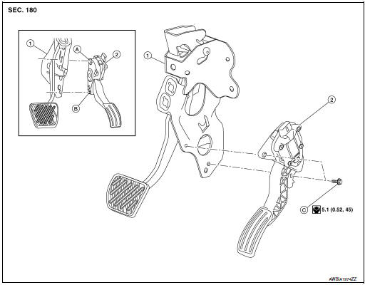
- Brake pedal
- Accelerator pedal assembly
- Locator hook
- Locator pin
- Bolt
Removal and Installation
REMOVAL
- Disconnect the harness connector from the accelerator pedal assembly.
- Remove the bolts, then remove accelerator pedal assembly.
CAUTION:
- Do not disassemble accelerator pedal assembly.
- Do not drop or impact accelerator pedal assembly.
- Do not expose accelerator pedal assembly to water.
INSTALLATION
Installation is in the reverse order of removal.
NOTE: When installing the accelerator pedal assembly, make sure to align locator hook and locator pin before installing bolts.
For inspection, refer to ACC-3, "Inspection".
Inspection
INSPECTION AFTER INSTALLATION
- Check that the accelerator pedal moves smoothly within the specified range.
Accelerator pedal stroke (A) : Refer to ACC-5, "Accelerator Control"
- Check the accelerator pedal height.
Accelerator pedal height (B) : Refer to ACC-5, "Accelerator Control"
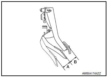
- accelerator pedal does not meet specified values, check brake pedal height. Refer to ACC-3, "Inspection".
- Depress and release the accelerator pedal to check that it returns quickly and smoothly to the original released position.
CAUTION:
- Whenever the harness connector of the accelerator pedal position sensor has been disconnected, perform "Accelerator Pedal Released Position Learning". Refer to EC-139, "Work Procedure".
- The accelerator pedal should operate smoothly without catching when the pedal operating force is released. The pedal should return smoothly to the fully raised position. The spring should be free from damage.
 Precaution
Precaution for Supplemental Restraint System (SRS) "AIR BAG" and "SEAT
BELT
PRE-TENSIONER"
The Supplemental Restraint System such as ŌĆ£AIR BAGŌĆØ and ŌĆ£SEAT BELT PRE-TENSIONE ...
 Service data and specifications
(SDS)
Service data and specifications
(SDS)
Accelerator Control
Accelerator pedal stroke (A)
49.6 - 52.4 (1.95 - 2.06
Pedal height difference between accelerator and brake (B)
35 - 45 (1.38 - 1.77)
...
Other materials:
Side air bag (satellite) sensor
Exploded View
Front door satellite sensor
Front side air bag satellite sensor
Rear side satellite sensor
Satellite sensor harness connector
Bolt
Nut
Pawl
Front
NOTE:
RH side shown, LH side similar.
Removal and Installation
WARNING:
Bef ...
DTC/circuit diagnosis
U1000 CAN COMM CIRCUIT
Description
CAN (Controller Area Network) is a serial communication system for real time
application. It is an on-vehicle
multiplex communication system with high data communication speed and excellent
error detection ability.
Many electronic control units are equipp ...
Preparation
Special Service Tool
The actual shape of the tools may differ from those illustrated here.
Tool number
(TechMate No.)
Tool name
Description
ŌĆö
(J-46532)
Brake height tool
Measuring brake pedal height
38-PFM92
( ŌĆö )
ProCutŌäó PFM Serie ...
