Nissan Rogue Service Manual: Basic inspection
DIAGNOSIS AND REPAIR WORK FLOW
Work Flow
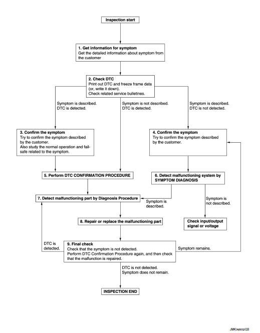
OVERALL SEQUENCE
DETAILED FLOW
1.GET INFORMATION FOR SYMPTOM
- Get detailed information from the customer about the symptom (the condition and the environment when the incident/malfunction occurs).
- Check operation condition of the function that is malfunctioning.
>> GO TO 2.
2.CHECK DTC
- Check DTC.
- Perform the following procedure if DTC is detected.
- Record DTC and freeze frame data. (Print them out using CONSULT.)
- Erase DTC.
- Study the relationship between the cause detected by DTC and the symptom described by the customer.
- Check related service bulletins for information.
Are any symptoms described and any DTC detected? Symptom is described, DTC is detected.>>GO TO 3.
Symptom is described, DTC is not detected.>>GO TO 4.
Symptom is not described, DTC is detected.>>GO TO 5.
3.CONFIRM THE SYMPTOM
Try to confirm the symptom described by the customer.
Also study the normal operation and fail-safe related to the symptom.
Verify relation between the symptom and the condition when the symptom is detected.
>> GO TO 5.
4.CONFIRM THE SYMPTOM
Try to confirm the symptom described by the customer.
Verify relation between the symptom and the condition when the symptom is detected.
>> GO TO 6.
5.PERFORM DTC CONFIRMATION PROCEDURE
Perform DTC CONFIRMATION PROCEDURE for the detected DTC and then check that DTC is detected again. At this time, always connect CONSULT to the vehicle and check self diagnostic results in real time.
If two or more DTCs are detected, refer to BCS-47, "DTC Inspection Priority Chart" (BCM) and determine trouble diagnosis order.
NOTE:
- Freeze frame data is useful if the DTC is not detected.
- Perform Component Function Check if DTC CONFIRMATION PROCEDURE
is not included on Service
Manual. This simplified check procedure is an effective alternative though
DTC cannot be detected during
this check.
If the result of Component Function Check is NG, it is the same as the detection of DTC by DTC CONFIRMATION PROCEDURE.
Is DTC detected? YES >> GO TO 7.
NO >> Check according to GI-41, "Intermittent Incident".
6.DETECT MALFUNCTIONING SYSTEM BY SYMPTOM DIAGNOSIS
Detect malfunctioning system according to SYMPTOM DIAGNOSIS based on the confirmed symptom in step 4, and determine the trouble diagnosis order based on possible causes and symptom.
Is the symptom described? YES >> GO TO 7.
NO >> Monitor input data from related sensors or check voltage of related module terminals using CONSULT.
7.DETECT MALFUNCTIONING PART BY DIAGNOSIS PROCEDURE
Inspect according to Diagnosis Procedure of the system.
Is malfunctioning part detected? YES >> GO TO 8.
NO >> Check according to GI-41, "Intermittent Incident".
8.REPAIR OR REPLACE THE MALFUNCTIONING PART
- Repair or replace the malfunctioning part.
- Reconnect parts or connectors disconnected during Diagnosis Procedure again after repair and replacement.
- Check DTC. If DTC is detected, erase it.
>> GO TO 9.
9.FINAL CHECK
When DTC is detected in step 2, perform DTC CONFIRMATION PROCEDURE again, and then check that the malfunction is repaired securely.
When symptom is described by the customer, refer to confirmed symptom in step 3 or 4, and check that the symptom is not detected.
Is DTC detected and does symptom remain? YES-1 >> DTC is detected: GO TO 7.
YES-2 >> Symptom remains: GO TO 4.
NO >> Before returning the vehicle to the customer, always erase DTC.
ADDITIONAL SERVICE WHEN REMOVING BATTERY NEGATIVE TERMINAL
Description
When the battery is disconnected from the negative terminal, it is necessary to perform initial setting to operate automatic back door control system normally.
NOTE: The following specified operations are not performed under the non-initialized condition.
- Automatic back door open/close function
- Anti-pinch function
Work Procedure
1.INITIALIZATION
- Fully close the back door manually. (When back door is already fully closed, this operation is not necessary).
- Perform automatic back door open/close operation of back door.
- Check for noise or malfunctioning during operation.
- Check that hazard lamp blinks and that warning buzzer operates.
NOTE: Never touch back door or allow foreign materials to be pinched in door when performing automatic back door open/close operation of back door until it is in the fully closed or fully open position. >> Inspection End.
ADDITIONAL SERVICE WHEN REPLACING BCM
Description
Perform the system initialization when replacing BCM, replacing Intelligent Key or registering an additional Intelligent Key.
Work Procedure
Refer to the CONSULT Immobilizer mode and follow the on-screen instructions.
ADDITIONAL SERVICE WHEN REPLACING AUTOMATIC BACK DOOR CONTROL UNIT
Description
When replacing control module or removing connector terminal, it is necessary to perform initial setting to operate automatic back door system normally.
NOTE: The following specified operations are not performed under the non-initialized condition.
- Automatic back door open/close function
- Anti-pinch function
Work Procedure
1.INITIALIZATION
- Fully close the back door manually. (When back door is already fully closed, this operation is not necessary.)
- Perform automatic back door open/close operation of back door.
- Check for noise or malfunctioning during operation.
- Check that hazard lamp blinks and that warning buzzer operates.
NOTE: Never touch back door or allow foreign materials to be pinched in door when performing automatic back door open/close operation of back door until it is in the fully closed or fully open position. >> Inspection End.
CALIBRATION OF AUTOMATIC BACK DOOR POSITION INFORMATION
Description
When the following work is performed, it is necessary to perform initial setting of automatic back door position information to operate automatic back door system.
- After removing and installing or replacing back door assembly
- After removing and installing or replacing spindle unit
- After adjustment or position change of the back door hinges or striker
Work Procedure
1.STEP 1
Fully close the back door manually.
>> GO TO 2.
2.STEP 2
- Select “AUTO BACK DOOR” using CONSULT.
- Select “RESET AUTO BACK DOOR STATUS” of “WORK SUPPORT” mode.
- Touch “START” to erase automatic back door position information.
>> GO TO 3.
3.STEP 3
Operate back door opener switch and perform automatic open operation.
NOTE: At this time, automatic operation of back door is performed at half speed.
>> GO TO 4.
4.STEP 4
- The back door fully opens.
- Check that hazard warning lamp blinks and automatic back door warning buzzer sounds normally.
Does hazard warning lamp blink and automatic back door warning buzzer sound normally? YES >> GO TO 5.
NO >> GO TO 1.
5.STEP 5
Fully close the back door.
>> Inspection End.
 Wiring diagram
POWER DOOR LOCK SYSTEM
Wiring Diagram
INTELLIGENT KEY SYSTEM
Wiring Diagram
AUTOMATIC BACK D ...
 DTC/circuit diagnosis
U1000 CAN COMM CIRCUIT
Description
Refer to LAN-8, "System Description".
DTC Logic
DTC DETECTION LOGIC
NOTE:
U1000 can be set if a module harness was disconnected and reconnected, perh ...
Other materials:
Rear shock absorber
Exploded View
Rear suspension member
Upper seat
Coil spring
Lower seat
Rubber washer (LH/RH)
Rear suspension arm
Rear shock absorber
Front
Removal and Installation
REMOVAL
Support the rear suspension arm using a suitable jack.
CAUTION:
Do not damage the rea ...
P0181 FTT sensor
DTC Description
DTC DETECTION LOGIC
DTC No.
CONSULT screen terms
(Trouble diagnosis content)
DTC detecting condition
P0181
FTT SENSOR
(Fuel temperature sensor ″A″ circuit range/
performance)
A
Rationally incorrect voltage from the sensor is sent ...
Outside mirrors
Outside mirrors
The outside mirror remote control will operate
only when the ignition switch is in the ACC or ON
position.
Move the small switch 1 to select the right or left
mirror. Adjust each mirror to the desired position
using the large switch 2 .
WARNING
Objects v ...
