Nissan Rogue Service Manual: DTC/circuit diagnosis
U1000 CAN COMM CIRCUIT
Description
Refer to LAN-8, "System Description".
DTC Logic
DTC DETECTION LOGIC
NOTE: U1000 can be set if a module harness was disconnected and reconnected, perhaps during a repair. Confirm that there are actual CAN diagnostic symptoms and a present DTC by performing the Self Diagnostic Result procedure.
|
CONSULT Dis |
DTC Detection Condition | Possible cause |
| CAN COMM CIRCUIT [U1000] | When any listed module cannot communicate with CAN communication signal continuously for 2 seconds or more with ignition switch ON | In CAN communication system, any item (or items)
of the following listed below is malfunctioning.
|
Diagnosis Procedure
1. PERFORM SELF DIAGNOSTIC
- Turn ignition switch ON and wait for 2 second or more.
- Check “SELF- DIAG RESULTS”.
Is “CAN COMM CIRCUIT” displayed? YES >> Perform CAN Diagnosis as described in DIAGNOSIS section of CONSULT Operation Manual.
NO >> Refer to GI-41, "Intermittent Incident".
U1010 CONTROL UNIT (CAN)
Description
CAN (Controller Area Network) is a serial communication line for real time applications. It is an on-vehicle multiplex communication line with high data communication speed and excellent error detection ability. Modern vehicle is equipped with many electronic control unit, and each control unit shares information and links with other control units during operation (not independent). In CAN communication, control units are connected with two communication lines (CAN-H and CAN-L) allowing a high rate of information transmission with less wiring. Each control unit transmits/receives data but selectively reads required data only.
CAN Communication Signal Chart. Refer to LAN-32, "CAN COMMUNICATION SYSTEM : CAN Communication Signal Chart".
DTC Logic
DTC DETECTION LOGIC
| DTC | CONSULT display description | DTC Detection Condition | Possible cause |
| U1010 | CONTROL UNIT(CAN) | Automatic back door control unit detected internal CAN communication circuit malfunction. | Automatic back door control module |
Diagnosis Procedure
1.REPLACE AUTOMATIC BACK DOOR CONTROL MODULE
When DTC “U1010: CONTROL UNIT(CAN)” is detected, replace automatic back door control module.
>> Replace automatic back door control module. Refer to DLK-276, "Removal and Installation".
B2401 IGNITION POWER SUPPLY CIRCUIT
DTC Logic
DTC DETECTION LOGIC
| DTC | CONSULT display description | DTC Detection Condition | Possible cause |
| B2401 | IGN OPEN | Automatic back door control module cannot detect ignition switch ON signal via CAN communication with BCM. |
|
DTC CONFIRMATION PROCEDURE
1.PERFORM DTC CONFIRMATION PROCEDURE
- Turn ignition switch ON.
- Operate automatic back door.
- Check "Self Diagnostic Result" mode of "AUTO BACK DOOR" using CONSULT.
Is DTC detected? YES >> Refer to DLK-106, "Diagnosis Procedure".
NO >> Inspection End.
Diagnosis Procedure
1.CHECK BCM OUTPUT SIGNAL
- Select "IPDM E/R" using CONSULT.
- Select "PUSH SW" in "Data Monitor" mode.
- Check that the function operates normally according to the following conditions.
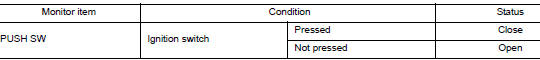
Is the inspection result normal? YES >> Replace automatic back door control module. Refer to DLK-276, "Removal and Installation".
NO >> Replace BCM. Refer to BCS-75, "Removal and Installation".
B2409 HALF LATCH SWITCH
DTC Logic
DTC DETECTION LOGIC
| DTC | CONSULT display description | DTC Detection Condition | Possible cause |
| B2409 | HALF LATCH SW | Automatic back door control module detects a malfunction of half latch switch during automatic operation of back door. |
|
DTC CONFIRMATION PROCEDURE
1.PERFORM DTC CONFIRMATION PROCEDURE
- Turn ignition switch ON.
- Operate automatic back door.
- Check "Self Diagnostic Result" mode of "AUTO BACK DOOR" using CONSULT.
Is DTC detected? YES >> Refer to DLK-107, "Diagnosis Procedure".
NO >> Inspection End.
Diagnosis Procedure
Regarding Wiring Diagram information, refer to DLK-86, "Wiring Diagram".
1.CHECK FOR FOREIGN MATERIALS IN BACK DOOR LOCK ASSEMBLY
Check for entry of foreign materials in back door lock assembly.
Is the inspection result normal? YES >> GO TO 2.
NO >> Remove foreign materials.
2.CHECK BACK DOOR OPEN/CLOSE OPERATION
Manually check open and close operation of back door.
Is the inspection result normal? YES >> GO TO 3.
NO >> Repair or replace the malfunction parts.
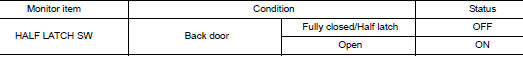
3.CHECK HALF LATCH SWITCH MONITOR ITEM
- Select "AUTO BACK DOOR" using CONSULT.
- Select "HALF LATCH SW" in "Data Monitor" mode.
- Check that the function operates normally according to the following conditions.
Is the inspection result normal? YES >> GO TO 8.
NO >> GO TO 4.
4.CHECK HALF LATCH SWITCH INPUT SIGNAL
- Turn ignition switch OFF.
- Disconnect back door lock assembly connector.
- Check voltage between back door lock assembly harness connector and ground.
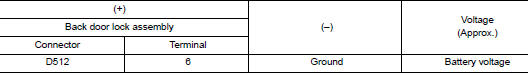
Is the inspection result normal? YES >> GO TO 6.
NO >> GO TO 5.
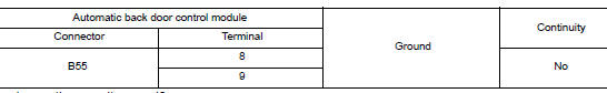
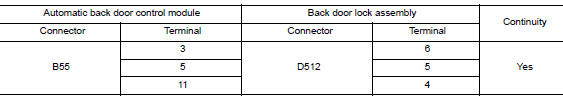
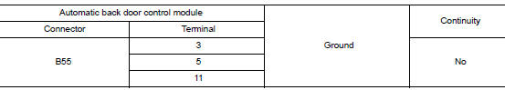
5.CHECK HALF LATCH SWITCH CIRCUIT
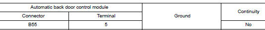
- Disconnect automatic back door control module connector.
- Check continuity between automatic back door control module harness connector and back door lock assembly harness connector.
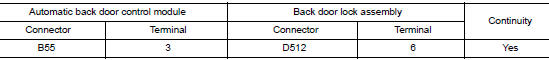
- Check continuity between automatic back door control module harness connector and ground.
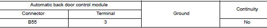
Is the inspection result normal? YES >> Replace automatic back door control module. Refer to DLK-276, "Removal and Installation".
NO >> Repair or replace harness.
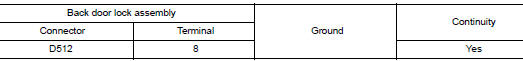
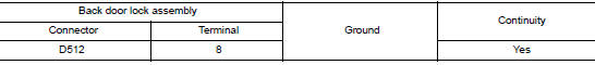
6.CHECK HALF LATCH SWITCH GROUND CIRCUIT
Check continuity between back door lock assembly harness connector and ground.
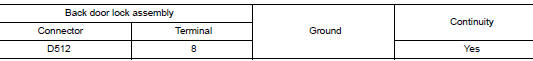
Is the inspection result normal? YES >> GO TO 7.
NO >> Repair or replace harness or connector.
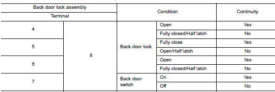
7.CHECK HALF LATCH SWITCH
Refer to DLK-108, "Component Inspection".
Is the inspection result normal? YES >> GO TO 8.
NO >> Replace back door lock assembly. Refer to DLK-263, "DOOR LOCK : Removal and Installation".
8.CHECK INTERMITTENT INCIDENT
Refer to GI-41, "Intermittent Incident".
>> Inspection End.
Component Inspection
COMPONENT INSPECTION
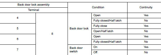
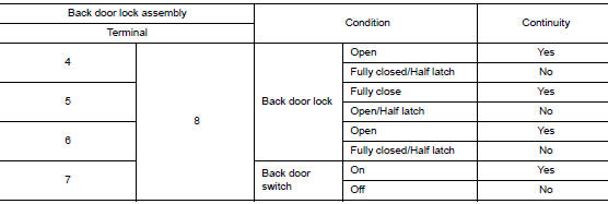
1.CHECK SWITCH
- Turn ignition switch OFF.
- Disconnect back door lock assembly connector.
- Check continuity between back door lock assembly terminals.
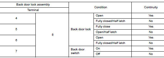
Is the inspection result normal? YES >> Inspection End.
NO >> Replace back door lock assembly. Refer to DLK-263, "DOOR LOCK : Removal and Installation".
B2416 TOUCH SENSOR RH
DTC Logic
DTC DETECTION LOGIC
| DTC | CONSULT display description | DTC Detection Condition | Possible cause |
| B2416 | TOUCH SEN R OPEN | Automatic back door control module detects a malfunction of touch sensor RH during automatic operation of back door. |
|
DTC CONFIRMATION PROCEDURE
1.PERFORM DTC CONFIRMATION PROCEDURE
- Turn ignition switch ON.
- Check "Self-Diagnostic Result" mode of "AUTO BACK DOOR" using CONSULT.
Is DTC detected? YES >> Refer to DLK-110, "Diagnosis Procedure".
NO >> Inspection End.
Diagnosis Procedure
Regarding Wiring Diagram information, refer to DLK-86, "Wiring Diagram".
1.CHECK INSTALLATION OF TOUCH SENSOR RH
Check that touch sensor RH is installed normally.
Refer to DLK-264, "TOUCH SENSOR : Removal and Installation".
Is the inspection result normal? YES >> GO TO 2.
NO >> Refer to DLK-264, "TOUCH SENSOR : Removal and Installation".
2.CHECK TOUCH SENSOR MONITOR ITEM
- Select "AUTO BACK DOOR" using CONSULT.
- Select "TOUCH SEN RH" in "Data Monitor" mode.
- Check that the function operates normally according to the following conditions.
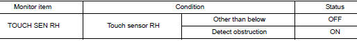
Is the inspection result normal? YES >> GO TO 8.
NO >> GO TO 3.
3.CHECK TOUCH SENSOR INPUT SIGNAL
- Turn ignition switch OFF.
- Check voltage between touch sensor RH harness connector and automatic back door control module harness connector.
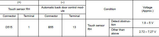
Is the inspection result normal? YES >> GO TO 5.
NO >> GO TO 4.
4.CHECK TOUCH SENSOR RH CIRCUIT
- Disconnect automatic back door control module and touch sensor RH connector.
- Check continuity between automatic back door control module harness connector and touch sensor RH harness connector.
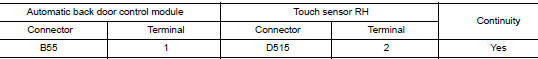
- Check continuity between automatic back door control module harness connector and ground.
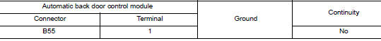
Is the inspection result normal? YES >> Replace automatic back door control module. Refer to DLK-276, "Removal and Installation".
NO >> Repair or replace harness.
5.CHECK TOUCH SENSOR RH GROUND CIRCUIT
- Disconnect automatic back door control module and touch sensor RH connector.
- Check continuity between automatic back door control module harness connector and touch sensor RH harness connector.
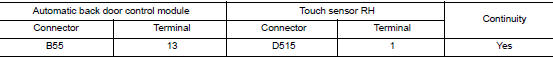
- Check continuity between automatic back door control module harness connector and ground.
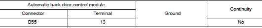
Is the inspection result normal? YES >> GO TO 6.
NO >> Repair or replace harness.
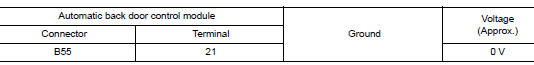
6.CHECK TOUCH SENSOR RH GROUND CIRCUIT 2
- Connect automatic back door control module and touch sensor RH connector.
- Check voltage between automatic back door control module harness connector and ground.
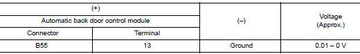
Is the inspection result normal? YES >> GO TO 7.
NO >> Replace automatic back door control module. Refer to DLK-276, "Removal and Installation".
7.CHECK TOUCH SENSOR RH
Refer to DLK-112, "Component Inspection".
Is the inspection result normal? YES >> GO TO 8.
NO >> Replace touch sensor RH. Refer to DLK-264, "TOUCH SENSOR : Removal and Installation".
8.CHECK INTERMITTENT INCIDENT
Refer to GI-41, "Intermittent Incident".
>> Inspection End.
Component Inspection
1.CHECK TOUCH SENSOR RH
- Turn ignition switch OFF.
- Disconnect touch sensor RH connector.
- Check resistance between touch sensor RH terminals.
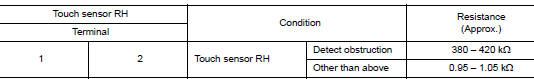
Is the inspection result normal? YES >> Inspection End.
NO >> Replace touch sensor RH. Refer to DLK-264, "TOUCH SENSOR : Removal and Installation".
B2417 TOUCH SENSOR LH
DTC Logic
DTC DETECTION LOGIC
| DTC | CONSULT display description | DTC Detection Condition | Possible cause |
| B2417 | TOUCH SEN L OPEN | Automatic back door control module detects a malfunction of touch sensor LH during automatic operation of back door. |
|
DTC CONFIRMATION PROCEDURE
1.PERFORM DTC CONFIRMATION PROCEDURE
- Turn ignition switch ON.
- Check "Self-Diagnostic Result" mode of "AUTO BACK DOOR" using CONSULT.
Is DTC detected? YES >> Refer to DLK-113, "Diagnosis Procedure".
NO >> Inspection End.
Diagnosis Procedure
Regarding Wiring Diagram information, refer to DLK-86, "Wiring Diagram".
1.CHECK INSTALLATION OF TOUCH SENSOR LH
Check that touch sensor LH is installed normally.
Refer to DLK-264, "TOUCH SENSOR : Removal and Installation".
Is the inspection result normal? YES >> GO TO 2.
NO >> Refer to DLK-264, "TOUCH SENSOR : Removal and Installation".
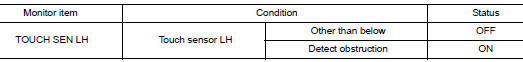
2.CHECK TOUCH SENSOR MONITOR ITEM
- Select "AUTO BACK DOOR" using CONSULT.
- Select "TOUCH SEN LH" in "Data Monitor" mode.
- Check that the function operates normally according to the following conditions.
Is the inspection result normal? YES >> GO TO 8.
NO >> GO TO 3.
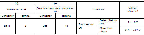
3.CHECK TOUCH SENSOR INPUT SIGNAL
- Turn ignition switch OFF.
- Check voltage between touch sensor LH harness connector and automatic back door control module harness connector.
Is the inspection result normal? YES >> GO TO 5.
NO >> GO TO 4.
4.CHECK TOUCH SENSOR LH CIRCUIT
- Disconnect automatic back door control module and touch sensor LH connector.
- Check continuity between automatic back door control module harness connector and touch sensor LH harness connector.
- Check continuity between automatic back door control module harness connector and ground.
Is the inspection result normal? YES >> Replace automatic back door control module. Refer to DLK-276, "Removal and Installation".
NO >> Repair or replace harness.
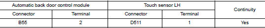
5.CHECK TOUCH SENSOR LH GROUND CIRCUIT
- Disconnect automatic back door control module and touch sensor LH connector.
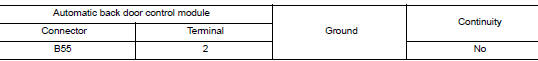
- Check continuity between automatic back door control module harness connector and touch sensor LH harness connector.
- Check continuity between automatic back door control module harness connector and ground.
Is the inspection result normal? YES >> GO TO 6.
NO >> Repair or replace harness.
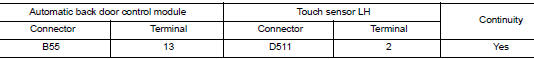
6.CHECK TOUCH SENSOR LH GROUND CIRCUIT 2
- Connect automatic back door control module and touch sensor LH connector.
- Check voltage between automatic back door control module harness connector and ground.
Is the inspection result normal? YES >> GO TO 7.
NO >> Replace automatic back door control module. Refer to DLK-276, "Removal and Installation".
7.CHECK TOUCH SENSOR LH
Refer to DLK-112, "Component Inspection".
Is the inspection result normal? YES >> GO TO 8.
NO >> Replace touch sensor LH. Refer to DLK-264, "TOUCH SENSOR : Removal and Installation"
8.CHECK INTERMITTENT INCIDENT
Refer to GI-41, "Intermittent Incident".
>> Inspection End.
Component Inspection
1.CHECK TOUCH SENSOR LH
- Turn ignition switch OFF.
- Disconnect touch sensor LH connector.
- Check resistance between touch sensor LH terminals.
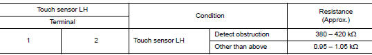
Is the inspection result normal? YES >> Inspection End.
NO >> Replace touch sensor LH. Refer to DLK-264, "TOUCH SENSOR : Removal and Installation".
B2419 OPEN SWITCH
DTC Logic
DTC DETECTION LOGIC
| DTC | CONSULT display description | DTC Detection Condition | Possible cause |
| B2419 | OPEN SW | Automatic back door control module detects a malfunction of open switch during automatic operation of back door. |
|
DTC CONFIRMATION PROCEDURE
1.PERFORM DTC CONFIRMATION PROCEDURE
- Turn ignition switch ON.
- Operate automatic back door.
- Check "Self-Diagnostic Result" mode of "AUTO BACK DOOR" using CONSULT.
Is DTC detected? YES >> Refer to DLK-116, "Diagnosis Procedure".
NO >> Inspection End.
Diagnosis Procedure
Regarding Wiring Diagram information, refer to DLK-86, "Wiring Diagram".
1.CHECK FOR FOREIGN MATERIALS IN BACK DOOR LOCK ASSEMBLY
Check for entry of foreign materials in back door lock assembly.
Is the inspection result normal? YES >> GO TO 2.
NO >> Remove foreign materials.
2.CHECK BACK DOOR OPEN/CLOSE OPERATION
Manually check open and close operation of back door.
Is the inspection result normal? YES >> GO TO 3.
NO >> Repair or replace the malfunctioning parts.
3.CHECK OPEN SWITCH SIGNAL
- Select "AUTO BACK DOOR" using CONSULT.
- Select "OPEN SW" in "Data Monitor" mode.
- Check that the function operates normally according to the following conditions.
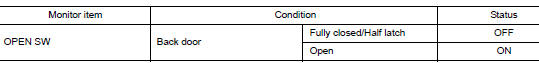
Is the inspection result normal? YES >> GO TO 8.
NO >> GO TO 4.
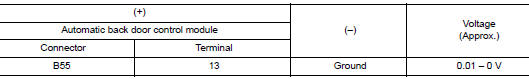
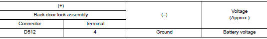
4.CHECK OPEN SWITCH INPUT SIGNAL
- Turn ignition switch OFF.
- Disconnect back door lock assembly connector.
- Check voltage between back door lock assembly harness connector and ground.
Is the inspection result normal? YES >> GO TO 6.
NO >> GO TO 5.
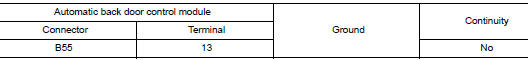
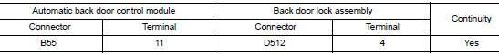
5.CHECK OPEN SWITCH CIRCUIT
- Disconnect automatic back door control module connector.
- Check continuity between automatic back door control module harness connector and back door lock assembly harness connector.
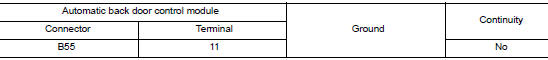
- Check continuity between automatic back door control module harness connector and ground.
Is the inspection result normal? YES >> Replace automatic back door control module. Refer to DLK-276, "Removal and Installation".
NO >> Repair or replace harness.
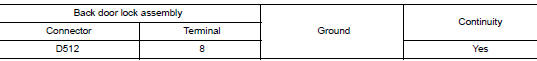
6.CHECK OPEN SWITCH GROUND CIRCUIT
Check continuity between back door lock assembly harness connector and ground.
Is the inspection result normal? YES >> GO TO 7.
NO >> Repair or replace harness.
7.CHECK OPEN SWITCH
Refer to DLK-108, "Component Inspection".
Is the inspection result normal? YES >> GO TO 8.
NO >> Replace back door lock assembly. Refer to DLK-263, "DOOR LOCK : Removal and Installation".
8.CHECK INTERMITTENT INCIDENT
Refer to GI-41, "Intermittent Incident".
>> Inspection End.
Component Inspection
COMPONENT INSPECTION
1.CHECK SWITCH
- Turn ignition switch OFF.
- Disconnect back door lock assembly connector.
- Check continuity between back door lock assembly terminals.
Is the inspection result normal? YES >> Inspection End.
NO >> Replace back door lock assembly. Refer to DLK-263, "DOOR LOCK : Removal and Installation".
B2420 CLOSE SWITCH
DTC Logic
DTC DETECTION LOGIC
| DTC | CONSULT display description | DTC Detection Condition | Possible cause |
| B2420 | CLOSE SW | Automatic back door control module detects a malfunction of close switch during automatic operation of back door. |
|
DTC CONFIRMATION PROCEDURE
1.PERFORM DTC CONFIRMATION PROCEDURE
- Turn ignition switch ON.
- Check "Self-Diagnostic Result" mode of "AUTO BACK DOOR" using CONSULT.
Is DTC detected? YES >> Refer to DLK-119, "Diagnosis Procedure".
NO >> Inspection End.
Diagnosis Procedure
Regarding Wiring Diagram information, refer to DLK-86, "Wiring Diagram".
1.CHECK FOR FOREIGN MATERIALS IN BACK DOOR LOCK ASSEMBLY
Check for entry of foreign materials in back door lock assembly.
Is the inspection result normal? YES >> GO TO 2.
NO >> Remove foreign materials.
2.CHECK BACK DOOR OPEN/CLOSE OPERATION
Manually check open and close operation of back door.
Is the inspection result normal? YES >> GO TO 3.
NO >> Repair or replace the malfunctioning parts.
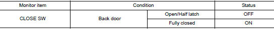
3.CHECK CLOSE SWITCH SIGNAL
- Select "AUTO BACK DOOR" using CONSULT.
- Select "CLOSE SW" in "Data Monitor" mode.
- Check that the function operates normally according to the following conditions.
Is the inspection result normal? YES >> GO TO 8.
NO >> GO TO 4.
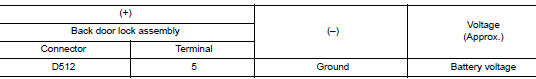
4.CHECK CLOSE SWITCH INPUT SIGNAL
- Turn ignition switch OFF.
- Disconnect back door lock assembly connector.
- Check voltage between back door lock assembly harness connector and ground.
Is the inspection result normal? YES >> GO TO 6.
NO >> GO TO 5.
5.CHECK CLOSE SWITCH CIRCUIT
- Disconnect automatic back door control module connector.
- Check continuity between automatic back door control module harness connector and back door lock assembly harness connector.
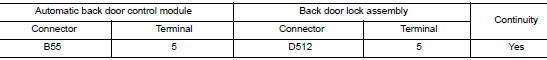
- Check continuity between automatic back door control module harness connector and ground.
Is the inspection result normal? YES >> Replace automatic back door control module. Refer to DLK-276, "Removal and Installation".
NO >> Repair or replace harness.
6.CHECK CLOSE SWITCH GROUND CIRCUIT
Check continuity between back door lock assembly harness connector and ground.
Is the inspection result normal? YES >> GO TO 7.
NO >> Repair or replace harness.
7.CHECK CLOSE SWITCH
Refer to DLK-108, "Component Inspection".
Is the inspection result normal? YES >> GO TO 8.
NO >> Replace back door lock assembly. Refer to DLK-263, "DOOR LOCK : Removal and Installation".
8.CHECK INTERMITTENT INCIDENT
Refer to GI-41, "Intermittent Incident".
>> Inspection End.
Component Inspection
COMPONENT INSPECTION
1.CHECK SWITCH
- Turn ignition switch OFF.
- Disconnect back door lock assembly.
- Check continuity between back door lock assembly terminals.
Is the inspection result normal? YES >> Inspection End.
NO >> Replace back door lock assembly. Refer to DLK-263, "DOOR LOCK : Removal and Installation".
B2422 BACK DOOR STATE
DTC Logic
DTC DETECTION LOGIC
| DTC | CONSULT display description | DTC Detection Condition | Possible cause |
| B2422 | BACK DOOR STATE | When the automatic back door control module detects back door position malfunction according to the pulse signal. |
|
DTC CONFIRMATION PROCEDURE
1.PERFORM DTC CONFIRMATION PROCEDURE
- Turn ignition switch ON.
- Operate automatic back door.
- Check “Self Diagnostic Result” mode of “AUTO BACK DOOR” using CONSULT.
Is DTC detected? YES >> Refer to DLK-122, "Diagnosis Procedure".
NO >> Inspection End.
Diagnosis Procedure
Regarding Wiring Diagram information, refer to DLK-86, "Wiring Diagram".
1.CALIBRATION OF AUTOMATIC BACK DOOR POSITION INFORMATION
- Perform initialization setting of automatic back door position
information.
Refer to DLK-102, "Work Procedure".
- Erase DTC, and then repeat “PERFORM DTC CONFIRMATION PROCEDURE”.
Is DTC detected? YES >> GO TO 2.
NO >> Inspection End.
2.CHECK INSTALLATION OF BACK DOOR ASSEMBLY
- Check that back door assembly is installed normally.
Refer to DLK-250, "BACK DOOR ASSEMBLY : Adjustment".
- Check back door assembly mechanism deformation, looseness, rattle, interference with other parts and pinched foreign materials.
Is the inspection result normal? YES >> GO TO 3.
NO >> Repair or replace the malfunctioning parts.
3.CHECK ENCODER SIGNAL
- Select “AUTOMATIC BACK DOOR” using CONSULT.
- Select “SPINDLE SENSOR LH” and “SPINDLE SENSOR RH” in “Data Monitor” mode.
- Check that the function operates normally according to the following conditions.
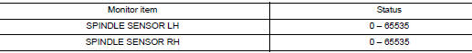
Is the difference between the 2 monitor items 10 or more? YES >> GO TO 4.
NO >> Replace automatic back door control module. Refer to DLK-276, "Removal and Installation".
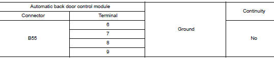
4.CHECK ENCODER POWER SUPPLY
- Turn ignition switch OFF.
- Disconnect spindle unit connector.
- Check voltage between spindle unit harness connector and ground.
Is the inspection result normal? YES >> GO TO 6.
NO >> GO TO 5.
5.CHECK ENCODER CIRCUIT
- Disconnect automatic back door control module connector.
- Check continuity between automatic back door control module harness connector and spindle unit harness connector.
- Check continuity between automatic back door control module harness connector and ground.
Is the inspection result normal? YES >> Replace automatic back door control module. Refer to DLK-276, "Removal and Installation".
NO >> Repair or replace harness.
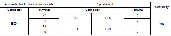
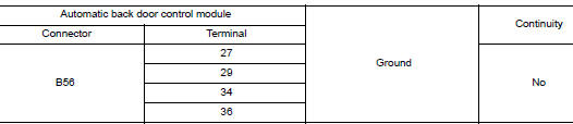
6.CHECK ENCODER CIRCUIT 2
- Disconnect automatic back door control module connector.
- Check continuity between automatic back door control module harness connector and spindle unit harness connector.
- Check continuity between automatic back door control module harness connector and ground.
Is the inspection result normal? YES >> GO TO 7.
NO >> Repair or replace harness.
7.CHECK ENCODER CIRCUIT 3
- Connect automatic back door control module and spindle unit connector
- Check continuity between automatic back door control module harness connector and ground.
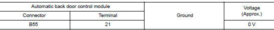
Is the inspection result normal? YES >> GO TO 8.
NO >> Replace automatic back door control module. Refer to DLK-276, "Removal and Installation".
8.CHECK INTERMITTENT INCIDENT
Refer to GI-41, "Intermittent Incident".
Is the inspection result normal? YES >> Replace automatic back door control module. Refer to DLK-276, "Removal and Installation".
NO >> Repair or replace the malfunctioning parts.
B2423 AUTOMATIC BACK DOOR MOTOR OPERATION TIME
DTC Logic
DTC DETECTION LOGIC
| DTC | CONSULT display description | DTC Detection Condition | Possible cause |
| B2423 | ABD MTR TIME OUT | When the automatic back door control module and spindle motor operate in the same direction for 180 seconds or more continuously. |
|
DTC CONFIRMATION PROCEDURE
1.PERFORM DTC CONFIRMATION PROCEDURE
- Turn ignition switch ON.
- Operate automatic back door.
- Check “Self-Diagnostic Result” mode of “AUTO BACK DOOR” using CONSULT.
Is DTC detected? YES >> Refer to DLK-125, "Diagnosis Procedure".
NO >> Inspection End.
Diagnosis Procedure
Regarding Wiring Diagram information, refer to DLK-86, "Wiring Diagram".
1.ERASE DTC
- At least 180 seconds are passed after automatic back door operation is inhibited.
- Erase DTC, and then repeat “PERFORM DTC CONFIRMATION PROCEDURE”.
Is DTC detected? YES >> GO TO 2.
NO >> Inspection End.
2.CHECK SPINDLE MOTOR CIRCUIT
- Turn ignition switch OFF.
- Disconnect automatic back door control module and spindle unit connector.
- . Check continuity between automatic back door control module harness connector and spindle unit harness connector.
- Check continuity between automatic back door control module harness connector and ground.
Is the inspection result normal? YES >> Replace automatic back door control module. Refer to DLK-276, "Removal and Installation".
NO >> Repair or replace harness.
B2426 ENCODER
DTC Logic
DTC DETECTION LOGIC
| DTC | CONSULT display description | DTC Detection Condition | Possible cause |
| B2426 | SPINDLE SENSOR LH | When the automatic back door control module can not receive the pulse signal from the encoder just after starting the open/close operation. |
|
DTC CONFIRMATION PROCEDURE
1.PERFORM DTC CONFIRMATION PROCEDURE
- Turn ignition switch ON.
- Operate automatic back door.
- Check “Self-Diagnostic Result” mode of “AUTO BACK DOOR” using CONSULT.
Is DTC detected? YES >> Refer to DLK-127, "Diagnosis Procedure".
NO >> Inspection End.
Diagnosis Procedure
Regarding Wiring Diagram information, refer to DLK-86, "Wiring Diagram".
1.CALIBRATION OF AUTOMATIC BACK DOOR POSITION INFORMATION
- Perform initialization setting of automatic back door position
information.
Refer to DLK-102, "Work Procedure".
- Erase DTC, and then repeat “PERFORM DTC CONFIRMATION PROCEDURE”.
Is DTC detected? YES >> GO TO 2.
NO >> Inspection End.
2.CHECK INSTALLATION OF BACK DOOR ASSEMBLY
- Check that back door assembly is installed normally.
Refer to DLK-250, "BACK DOOR ASSEMBLY : Adjustment".
- Check back door assembly mechanism deformation, looseness, rattle, interference with other parts, and pinched foreign materials.
Is the inspection result normal? YES >> GO TO 3.
NO >> Repair or replace the malfunctioning parts.
3.CHECK ENCODER SIGNAL
- Select “AUTO BACK DOOR” using CONSULT.
- Select “SPINDLE LH ENCODER A” and “SPINDLE LH ENCODER B” in “Data Monitor” mode.
- Check that the function operates normally according to the following conditions.
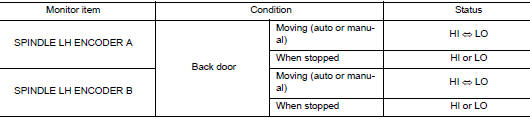
Is the inspection result normal? YES >> GO TO 4.
NO >> Replace automatic back door control module. Refer to DLK-276, "Removal and Installation".
4.CHECK ENCODER POWER SUPPLY
- Turn ignition switch OFF.
- Disconnect spindle unit LH connector.
- Check voltage between spindle unit LH harness connector and ground.
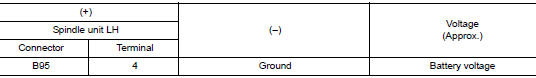
Is the inspection result normal? YES >> GO TO 6.
NO >> GO TO 5.
5.CHECK ENCODER CIRCUIT
- Disconnect automatic back door control module connector.
- Check continuity between automatic back door control module harness connector and spindle unit LH harness connector.
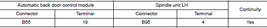
- Check continuity between automatic back door control module harness connector and ground.
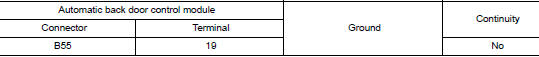
Is the inspection result normal? YES >> Replace automatic back door control module. Refer to DLK-276, "Removal and Installation".
NO >> Repair or replace harness.
6.CHECK ENCODER CIRCUIT 2
- Disconnect automatic back door control module connector.
- Check continuity between automatic back door control module harness connector and spindle unit LH harness connector.
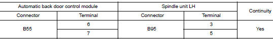
- Check continuity between automatic back door control module harness connector and ground.
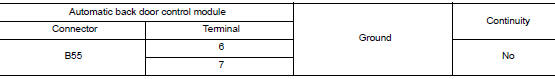
Is the inspection result normal? YES >> GO TO 7.
NO >> Repair or replace harness.
7.CHECK ENCODER CIRCUIT 3
- Connect automatic back door control module and spindle unit LH connector.
- Check continuity between automatic back door control module harness connector and ground.
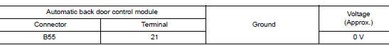
Is the inspection result normal? YES >> GO TO 8.
NO >> Replace automatic back door control module. Refer to DLK-276, "Removal and Installation".
8.CHECK INTERMITTENT INCIDENT
Refer to GI-41, "Intermittent Incident".
Is the inspection result normal? YES >> Replace automatic back door control module. Refer to DLK-276, "Removal and Installation".
NO >> Repair or replace the malfunctioning parts.
B2427 ENCODER
DTC Logic
DTC DETECTION LOGIC
| DTC | CONSULT display description | DTC Detection Condition | Possible cause |
| B2427 | SPINDLE SENSOR RH | When the automatic back door control module can not receive the pulse signal from the encoder just after starting the open/close operation. |
|
DTC CONFIRMATION PROCEDURE
1.PERFORM DTC CONFIRMATION PROCEDURE
- Turn ignition switch ON.
- Operate automatic back door.
- Check “Self-Diagnostic Result” mode of “AUTO BACK DOOR” using CONSULT.
Is DTC detected? YES >> Refer to DLK-130, "Diagnosis Procedure".
NO >> Inspection End.
Diagnosis Procedure
Regarding Wiring Diagram information, refer to DLK-86, "Wiring Diagram".
1.CALIBRATION OF AUTOMATIC BACK DOOR POSITION INFORMATION
- Perform initialization setting of automatic back door position
information.
Refer to DLK-102, "Work Procedure".
- Erase DTC, and then repeat “PERFORM DTC CONFIRMATION PROCEDURE”.
Is DTC detected? YES >> GO TO 2.
NO >> Inspection End.
2.CHECK INSTALLATION OF BACK DOOR ASSEMBLY
- Check that back door assembly is installed normally.
Refer to DLK-250, "BACK DOOR ASSEMBLY : Adjustment".
- Check back door assembly mechanism deformation, looseness, rattle, interference with other parts, and pinched foreign materials.
Is the inspection result normal? YES >> GO TO 3.
NO >> Repair or replace the malfunctioning parts.
3.CHECK ENCODER SIGNAL
- Select “AUTO BACK DOOR” using CONSULT.
- Select “SPINDLE RH ENCODER A” and “SPINDLE RH ENCODER B” in “Data Monitor” mode.
- Check that the function operates normally according to the following conditions.
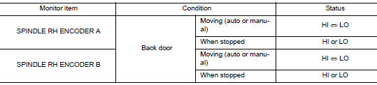
Is the inspection result normal? YES >> GO TO 4.
NO >> Replace automatic back door control module. Refer to DLK-276, "Removal and Installation".
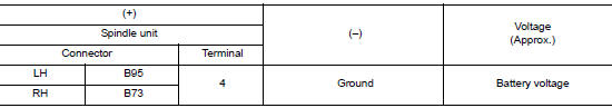
4.CHECK ENCODER POWER SUPPLY
- Turn ignition switch OFF.
- Disconnect spindle unit RH connector.
- Check voltage between spindle unit RH harness connector and ground.
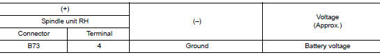
Is the inspection result normal? YES >> GO TO 6.
NO >> GO TO 5.
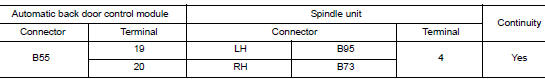
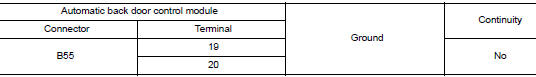
5.CHECK ENCODER CIRCUIT
- Disconnect automatic back door control module connector.
- Check continuity between automatic back door control module harness connector and spindle unit RH harness connector.
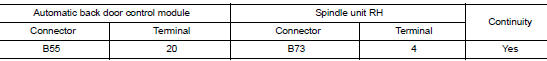
- Check continuity between automatic back door control module harness connector and ground.
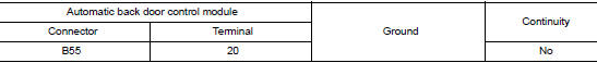
Is the inspection result normal? YES >> Replace automatic back door control module. Refer to DLK-276, "Removal and Installation".
NO >> Repair or replace harness.
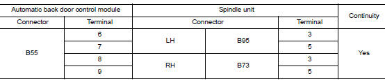
6.CHECK ENCODER CIRCUIT 2
- Disconnect automatic back door control module connector.
- Check continuity between automatic back door control module harness connector and spindle unit RH harness connector.
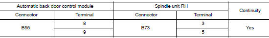
- Check continuity between automatic back door control module harness connector and ground.
Is the inspection result normal? YES >> GO TO 7.
NO >> Repair or replace harness.
7.CHECK ENCODER CIRCUIT 3
- Connect automatic back door control module spindle unit RH connector.
- Check continuity between automatic back door control module harness connector and ground.
Is the inspection result normal? YES >> GO TO 8.
NO >> Replace automatic back door control module. Refer to DLK-276, "Removal and Installation".
8.CHECK INTERMITTENT INCIDENT
Refer to GI-41, "Intermittent Incident".
Is the inspection result normal? YES >> Replace automatic back door control module. Refer to DLK-276, "Removal and Installation".
NO >> Repair or replace the malfunctioning parts.
B2428 AUTOMATIC BACK DOOR CONTROL UNIT
DTC Logic
DTC DETECTION LOGIC
| DTC | CONSULT display description | DTC Detection Condition | Possible cause |
| B2428 | AUTO BACK DR CNT UNIT | Automatic back door control module detected CPU malfunction | Automatic back door control modul |
Diagnosis Procedure
1.REPLACE AUTOMATIC BACK DOOR CONTROL MODULE
When DTC [B2428] is detected, replace automatic back door control module.
>> Replace automatic back door control module. Refer to DLK-276, "Removal and Installation".
B242A CLOSURE CONDITION
DTC Logic
DTC DETECTION LOGIC
| DTC | CONSULT display description | DTC Detection Condition | Possible cause |
| B242A | CLSR CONDITION | Automatic back door control module detects malfunctions of open switch, close switch and half latch switch when auto closure of back door operates. |
|
DTC CONFIRMATION PROCEDURE
1.PERFORM DTC CONFIRMATION PROCEDURE
- Turn ignition switch ON.
- Operate back door auto closure operation.
- Check "Self-Diagnostic Result" mode of "AUTO BACK DOOR" using CONSULT.
Is DTC detected? YES >> Refer to DLK-134, "Diagnosis Procedure".
NO >> Inspection End.
Diagnosis Procedure
Regarding Wiring Diagram information, refer to DLK-86, "Wiring Diagram".
1.CHECK FOR FOREIGN MATERIALS IN BACK DOOR LOCK ASSEMBLY
Check for entry of foreign materials in back door lock assembly.
Is the inspection result normal? YES >> GO TO 2.
NO >> Remove foreign materials.
2.CHECK BACK DOOR OPEN/CLOSE OPERATION
Manually check open and close operation of back door.
Is the inspection result normal? YES >> GO TO 3.
NO >> Repair or replace the malfunctioning parts.
3.CHECK MONITOR ITEM
- Select "AUTO BACK DOOR" using CONSULT.
- Select "HALF LATCH SW", "OPEN SW" and "CLOSE SW" in "Data Monitor" mode.
- Check that the function operates normally according to the following conditions.
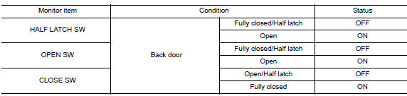
Is the inspection result normal? YES >> GO TO 8.
NO >> GO TO 4.
4.CHECK SWITCH INPUT SIGNAL
- Turn ignition switch OFF.
- Disconnect back door lock assembly connector.
- Check voltage between back door lock assembly harness connector and ground.
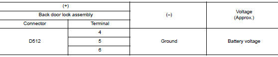
Is the inspection result normal? YES >> GO TO 6.
NO >> GO TO 5.
5.CHECK SWITCH CIRCUIT
- Disconnect automatic back door control module connector.
- Check continuity between automatic back door control module harness connector and back door lock assembly harness connector.
- Check continuity between automatic back door control module harness connector and ground.
Is the inspection result normal? YES >> Replace automatic back door control module. Refer to DLK-276, "Removal and Installation".
NO >> Repair or replace harness.
6.CHECK SWITCH GROUND CIRCUIT
Check continuity between back door lock assembly harness connector and ground.
Is the inspection result normal? YES >> GO TO 7.
NO >> Repair or replace harness or connector.
7.CHECK SWITCH
Refer to DLK-108, "Component Inspection".
Is the inspection result normal? YES >> GO TO 8.
NO >> Replace back door lock assembly. Refer to DLK-263, "DOOR LOCK : Removal and Installation".
8.CHECK INTERMITTENT INCIDENT
Refer to GI-41, "Intermittent Incident".
>> Inspection End.
Component Inspection
COMPONENT INSPECTION
1.CHECK SWITCH
- Turn ignition switch OFF.
- Disconnect back door lock assembly connector.
- Check continuity between back door lock assembly terminals.
Is the inspection result normal? YES >> Inspection End.
NO >> Replace back door lock assembly. Refer to DLK-263, "DOOR LOCK : Removal and Installation".
B2621 INSIDE ANTENNA
DTC Logic
DTC DETECTION LOGIC
| DTC | CONSULT display description | DTC Detection Condition | Possible cause |
| B2621 | INSIDE ANTENNA | An excessive high or low voltage from inside antenna (instrument center) is sent to BCM. |
|
DTC CONFIRMATION PROCEDURE
1.PERFORM DTC CONFIRMATION PROCEDURE
- Select “INTELLIGENT KEY” of “BCM” using CONSULT.
- Select “INSIDE ANT DIAGNOSIS” in “WORK SUPPORT” mode.
- Perform inside key antenna (“INSIDE ANT DIAGNOSIS”) on “Work support” of “INTELLIGENT KEY”.
- Check BCM for DTC.
Is inside key antenna DTC detected? YES >> Refer to DLK-137, "Diagnosis Procedure".
NO >> Inside key antenna (instrument center) is OK.
Diagnosis Procedure
Regarding Wiring Diagram information, refer to DLK-69, "Wiring Diagram".
1.CHECK INSIDE KEY ANTENNA INPUT SIGNAL 1
- Turn ignition switch OFF.
- . Check signal between BCM harness connector and ground using oscilloscope.
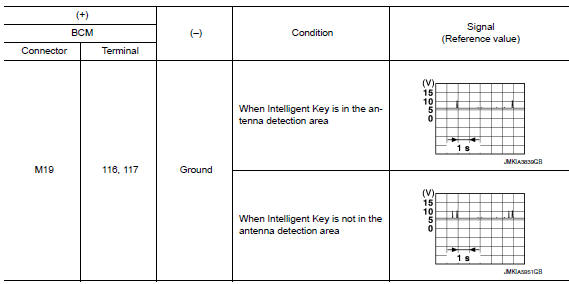
Is the inspection result normal? YES >> Replace BCM. Refer to BCS-75, "Removal and Installation".
NO >> GO TO 2.
2.CHECK INSIDE KEY ANTENNA CIRCUIT
- Disconnect BCM connector and inside key antenna (instrument center) connector.
- Check continuity between BCM harness connector and inside key antenna (instrument center) harness connector.
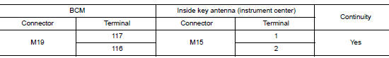
- Check continuity between BCM harness connector and ground.
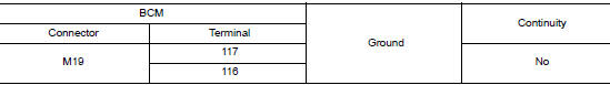
Is the inspection result normal? YES >> GO TO 3.
NO >> Repair or replace harness.
3.CHECK INSIDE KEY ANTENNA INPUT SIGNAL 2
- Replace inside key antenna (instrument center). (New antenna or other antenna)
- Connect BCM connector and inside key antenna (instrument center) connector.
- Check signal between BCM harness connector and ground using oscilloscope.
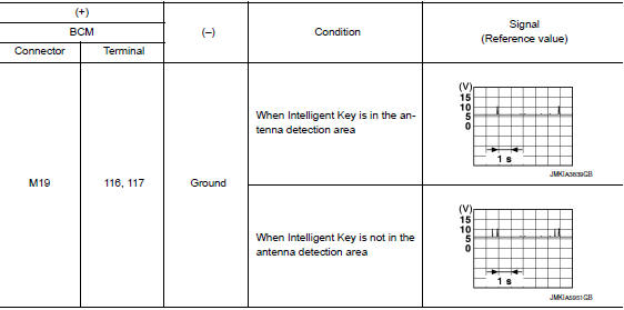
Is the inspection result normal? YES >> Replace inside key antenna (instrument center).
NO >> Replace BCM. Refer to BCS-75, "Removal and Installation".
B2622 INSIDE ANTENNA
DTC Logic
DTC DETECTION LOGIC
| DTC | CONSULT display description | DTC Detection Condition | Possible cause |
| B2622 | INSIDE ANTENNA | An excessive high or low voltage from inside antenna (console) is sent to BCM. |
|
DTC CONFIRMATION PROCEDURE
1.PERFORM DTC CONFIRMATION PROCEDURE
- Select "INTELLIGENT KEY" of "BCM" using CONSULT.
- Select "INSIDE ANT DIAGNOSIS" in "Work support" mode.
- Perform inside key antenna ("INSIDE ANT DIAGNOSIS") on "Work support" of INTELLIGENT KEY.
- Check BCM for DTC.
Is inside key antenna DTC detected? YES >> Refer to DLK-139, "Diagnosis Procedure".
NO >> Inside key antenna (console) is OK.
Diagnosis Procedure
Regarding Wiring Diagram information, refer to DLK-69, "Wiring Diagram".
1.CHECK INSIDE KEY ANTENNA INPUT SIGNAL 1
- Turn ignition switch OFF.
- Check signal between BCM harness connector and ground using oscilloscope.
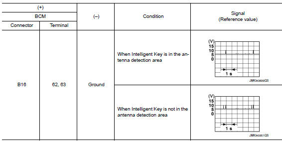
Is the inspection result normal? YES >> Replace BCM. Refer to BCS-75, "Removal and Installation".
NO >> GO TO 2.
2.CHECK INSIDE KEY ANTENNA CIRCUIT
- Disconnect BCM connector and inside key antenna (console) connector.
- Check continuity between BCM harness connector and inside key antenna (console) harness connector.
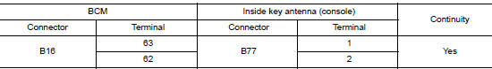
- Check continuity between BCM harness connector and ground.
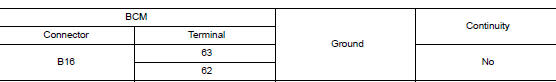
Is the inspection result normal? YES >> GO TO 3.
NO >> Repair or replace harness.
3.CHECK INSIDE KEY ANTENNA INPUT SIGNAL 2
- Replace inside key antenna (console). (New antenna or other antenna)
- Connect BCM connector and inside key antenna (console) connector.
- Check signal between BCM harness connector and ground using oscilloscope.
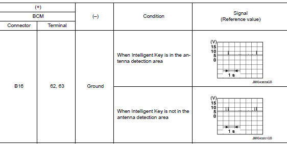
Is the inspection result normal? YES >> Replace inside key antenna (console). Refer to DLK-271, "CONSOLE : Removal and Installation".
NO >> Replace BCM. Refer to BCS-75, "Remova
 Basic inspection
DIAGNOSIS AND REPAIR WORK FLOW
Work Flow
OVERALL SEQUENCE
DETAILED FLOW
1.GET INFORMATION FOR SYMPTOM
Get detailed information from the customer about the symptom (the
condition a ...
 Symptom diagnosis
INTELLIGENT KEY SYSTEM SYMPTOMS
Symptom Table
CAUTION:
Perform the self-diagnosis with CONSULT before the symptom diagnosis. Perform
the trouble diagnosis
if any DTC is detected.
Sym ...
Other materials:
Service data and specifications (SDS)
Steering Wheel
Steering Angle
Steering Column
STEERING COLUMN LENGTH
STEERING COLUMN ROTATING TORQUE
TILT MECHANISM OPERATING RANGE
Steering Gear
STEERING OUTER SOCKET AND INNER SOCKET
INNER AND OUTER SOCKET LENGTH
RACK STROKE
RACK SLIDING FORCE
...
Preparation
Special Service Tool
The actual shape of the tools may differ from those illustrated here.
Tool number
(TechMate No.)
Tool name
Description
—
(J-46534)
Trim Tool Set
Removing trim components
—
(1-20-2721-1-IF)
Distance Sensor Ali ...
Unit removal and installation
FRONT SUSPENSION MEMBER
Exploded View
Front suspension member
Strut mounting bearing
Rebound stopper insulator
Rebound stopper
Removal and Installation
REMOVAL
Remove the wheel and tire using power tool. Refer to WT-60,
"Removal and Installation&quo ...
