Nissan Rogue Service Manual: Unit removal and installation
FRONT SUSPENSION MEMBER
Exploded View
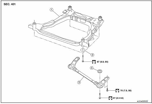
- Front suspension member
- Strut mounting bearing
- Rebound stopper insulator
- Rebound stopper
Removal and Installation
REMOVAL
- Remove the wheel and tire using power tool. Refer to WT-60, "Removal and Installation".
- Remove side under cover. Refer to EXT-37, "ENGINE UNDER COVER : Removal and Installation".
- Remove the bolt and separate the front wheel sensor from the steering knuckle. Separate the harness from the brackets and position aside. Refer to BRC-132, "FRONT WHEEL SENSOR : Exploded View".
CAUTION:
- Failure to separate the front wheel sensor from the steering knuckle may result in damage to the front wheel sensor.
- Pull out the front wheel sensor, being careful to turn it as little as possible. Do not pull on wheel sensor harness.
- Remove the nut and separate the stabilizer connecting rod from the strut bracket.
- Remove the cotter pin and nut, and separate the outer socket from the steering knuckle.
- Remove the bolt and separate steering column yoke from steering gear. Refer to ST-12, "Exploded View".
- Remove transverse link from steering knuckle. Refer to FAX-9, "Exploded View" (FWD), FAX-40, "Exploded View" (AWD).
- Remove rear torque rod. Refer to EM-81, "Exploded View".
- Set suitable jack front suspension member.
- Remove front suspension member stay from vehicle.
- Remove bolts and nuts of front suspension member.
- Gradually lower jack to remove front suspension assembly from
vehicle.
CAUTION: Secure suspension assembly to suitable jack while removing it.
- Remove bolts and nuts, and then remove transverse link, stabilizer bar from front suspension member.
INSTALLATION
Installation is in the reverse order of removal.
- Install the suspension member bolts in the order shown.
1-2 temporary tightening
3-5 torque to specification Refer to FSU-20, "Exploded View".
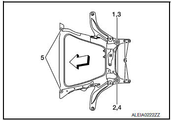
 : Front
- Perform final tightening of installation position between front suspension member and transverse links (rubber bushing) under unladen condition with tires on level ground.
- Check wheel sensor harness for proper connection. Refer to BRC- 132, "FRONT WHEEL SENSOR : Exploded View".
Inspection
INSPECTION AFTER REMOVAL
Check the front suspension member for significant deformation, cracks, or damages. Replace it if necessary.
INSPECTION AFTER INSTALLATION
Check wheel alignment. Refer to FSU-7, "Inspection".
 Removal and installation
FRONT COIL SPRING AND STRUT
Exploded View
Strut mount insulator
Rotary stop
Front spring upper rubber seat
Front suspension bound bumper
Front spring
Front spring lower ru ...
 Unit disassembly and assembly
FRONT COIL SPRING AND STRUT
Exploded View
Strut mount insulator
Rotary Stop
Front spring upper rubber seat
Front suspension bound bumper
Front spring
Front spring lo ...
Other materials:
Hill start assist system
Hill start assist system
WARNING
Never rely solely on the hill start assist
system to prevent the vehicle from moving
backward on a hill. Always drive
carefully and attentively. Depress the
brake pedal when the vehicle is stopped
on a steep hill. Be especial ...
Basic inspection
COLLISION DIAGNOSIS
FOR FRONTAL COLLISION
FOR FRONTAL COLLISION : When SRS is activated in a collision
CAUTION:
Due to varying models and option levels, not all parts listed in the chart below
apply to all vehicles.
WORK PROCEDURE
Before performing any of the following steps, ensure ...
Trouble diagnosis - specification value
Description
The specification (SP) value indicates the tolerance of the value that is
displayed in ÔÇťSPECÔÇŁ of ÔÇťDATA MONITORÔÇŁ
mode of CONSULT during normal operation of the Engine Control System. When the
value in ÔÇťSPECÔÇŁ of
ÔÇťDATA MONITORÔÇŁ mode is within the SP value, the Engine ...
