Nissan Rogue Service Manual: Removal and installation
FRONT COIL SPRING AND STRUT
Exploded View
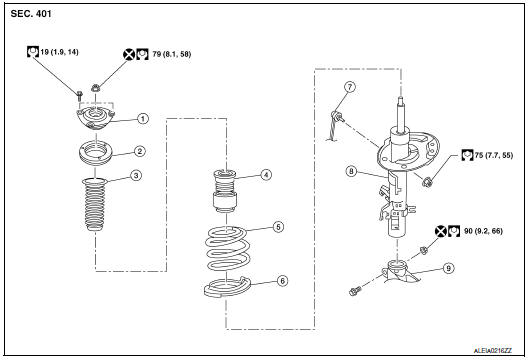
- Strut mount insulator
- Rotary stop
- Front spring upper rubber seat
- Front suspension bound bumper
- Front spring
- Front spring lower rubber seat
- Stabilizer connecting rod
- Strut
- Steering knuckle
Removal and Installation
REMOVAL
- Remove the wheel and tire using power tool. Refer to WT-60, "Removal and Installation".
- Remove the brake hose lock plate from strut.
- Remove the bolt and separate the front wheel sensor from the steering knuckle. Separate the harness from the brackets and position aside. Refer to BRC-132, "FRONT WHEEL SENSOR : Exploded View".
CAUTION:
- Failure to separate the front wheel sensor from the steering knuckle may result in damage to the front wheel sensor.
- Pull out the front wheel sensor, being careful to turn it as little as possible. Do not pull on wheel sensor harness.
- Remove torque member bolts, leaving the brake hose attached. Position
brake caliper aside with wire.
Refer to BR-35, "BRAKE CALIPER ASSEMBLY (1 PISTON TYPE) : Exploded View" (1 PISTON TYPE), or BR-39, "BRAKE CALIPER ASSEMBLY (2 PISTON TYPE) : Exploded View" (2 PISTON TYPE).
- Put alignment marks on the disc brake rotor and on the wheel hub
and bearing. Remove the disc brake
rotor.
CAUTION: Do not drop the disc brake rotor.
- Remove the cotter pin from the drive shaft.
- Remove the nut retainer from the wheel hub lock nut.
- Loosen the wheel hub lock nut using power tool.
- Tap wheel hub lock nut with a piece of wood to disengage wheel
hub and bearing from drive shaft.
NOTE: Use a suitable puller if wheel hub and bearing and drive shaft cannot be separated even after performing the above procedure.
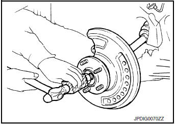
- Remove the wheel hub lock nut.
- Separate drive shaft from wheel hub and bearing.
- Remove the nut and separate the stabilizer connecting rod from the strut bracket.
- Remove the nut and separate the outer socket from the steering knuckle.
- Remove the upper nut and bolt from steering knuckle. Refer to FAX-9, "Exploded View".
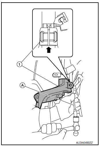
- Open the slot using a suitable tool (A). Separate the steering
knuckle (1) from the front coil spring and strut.
CAUTION: Do not drop steering knuckle.
- Remove the lower nut and bolt from the steering knuckle. Separate transverse link from the steering knuckle. Refer to FAX-9, "Exploded View".
- Remove the cowl top cover plug to access the upper strut bolt.
- Remove the upper strut bolts and the front coil spring and strut.
- Inspect the components. Refer to FSU-6, "Inspection".
INSTALLATION
CAUTION:
- Do not reuse the wheel hub lock nut.
- Do not reuse the cotter pin.
- Do not reuse steering knuckle upper bolt.
- Do not reuse steering knuckle lower nut.
Installation is in the reverse order of removal.
- Adjust the neutral position of the steering angle sensor. Refer to BRC-70, "Work Procedure".
- After replacing strut, always follow the disposal procedure to discard the strut. Refer to FSU-24, "Disposal".
- Perform the inspection after installation. Refer to FSU-6, "Inspection".
Inspection
INSPECTION AFTER REMOVAL
Strut
Check the following items, and replace the parts if necessary.
- Strut for deformation, cracks or damage
- Piston rod for damage, uneven wear or distortion
- Oil leakage
Strut Mounting Insulator and Rubber Parts Inspection
Check strut mounting insulator for cracks and rubber parts for wear. Replace it if necessary.
Coil Spring
Check coil spring for cracks, wear or damage. Replace it if necessary.
INSPECTION AFTER INSTALLATION
Check wheel alignment. Refer to FSU-7, "Inspection".
TRANSVERSE LINK
Exploded View
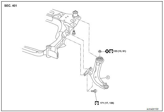
- Transverse link
Removal and Installation
REMOVAL
- Remove the wheel and tires using power tool. Refer to WT-60, "Removal and Installation".
- Remove the engine undercover. Refer to EXT-37, "ENGINE UNDER COVER : Removal and Installation".
- Remove the steering knuckle lower bolt and nut. Refer to FSU-17, "Exploded View"
- Remove the nut and separate the stabilizer connecting rod from the strut bracket.
- Remove transverse link bolts from suspension member, and remove
transverse link.
NOTE: Transverse link cannot be removed before the stabilizer bar is positioned out of the way because the rear bolt (
 ). Refer to
FSU-14, "Exploded View".
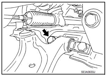
INSPECTION AFTER REMOVAL
Check the following items, and replace the components as necessary.
Ball Joint Inspection
Manually move ball joint to confirm it moves smoothly with no binding.
Transverse Link
- Check the transverse link and bushing for deformation, cracks or damage.
- Check the ball joint boot for cracks or other damage, and also for grease leaks.
Swing Torque
- Move the ball joint at least ten times by hand to check for smooth movement with no binding.
- Hook the Tool (A) on the on ball joint (B). Confirm the measurement value is within specifications when the ball joint begins moving.
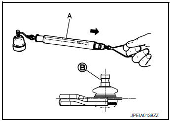
Tool number : ÔÇô (J-44372)
Swing torque : Refer to FSU-26, "Ball Joint".
Rotating torque : Refer to FSU-26, "Ball Joint"
- If swing torque or rotating torque exceeds standard range, replace the transverse link.
Axial End Play
- Move the ball joint at least ten times by hand to check for smooth movement.
- Move the tip of the ball joint in the axial direction to check for looseness.
Axial end play : Refer to FSU-26, "Ball Joint".
- If the axial end play exceeds the standard value, replace the transverse link.
INSTALLATION
Installation is in the reverse order of removal.
- Perform final tightening of nuts and bolts under unladen conditions with tires on level ground.
INSPECTION AFTER INSTALLATION
- Adjust neutral position of the steering angle sensor. Refer to BRC-70, "Work Procedure".
- Check the wheel alignment. Refer to FSU-7, "Inspection".
FRONT STABILIZER
Exploded View
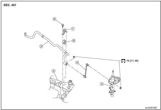
- Stabilizer clamp
- Stabilizer bar
- Front suspension member
- Strut
- Stabilizer connecting rod
- Stabilizer bushing
- Refer to Installation
Removal and Installation
REMOVAL
- Remove the wheel and tire using power tool. Refer to WT-60, "Removal and Installation".
- Remove the engine side under cover. Refer to EXT-37, "ENGINE UNDER COVER : Removal and Installation".
- Set suitable jack under front suspension member.
- Remove stabilizer connecting rod.
- Remove steering outer socket from steering knuckle. Refer to ST-14, "Exploded View".
- Remove front exhaust mount. Refer to EX-5, "Exploded View".
- Remove catalytic converter. Refer to EX-5, "Exploded View".
- Remove rear torque rod. Refer to EM-81, "Exploded View".
- Remove front suspension member stay and rubber stopper
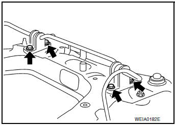
- Gradually lower jack front suspension member in order to remove stabilizer clamp bolts.
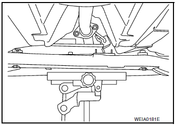
- Remove stabilizer clamp bolts (
 ), and then remove stabilizer
clamp and stabilizer bushing from front suspension member.
 - Remove stabilizer bar.
INSTALLATION
Installation is in the reverse order of removal.
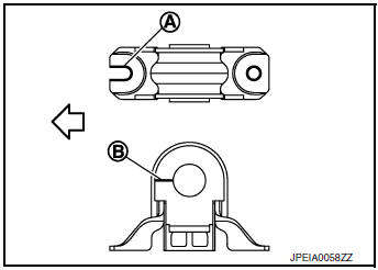
- Install stabilizer clamp so that notch (A) is facing front of vehicle
(
 ).
). - Install stabilizer bushing so that slit (B) is facing front of
vehicle
(
 ).
).
- Install the stabilizer clamp bolts in the order of 1 to 5 as shown.
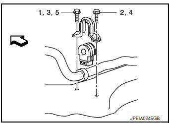
Manual tightening : 1
Temporary tightening : 2 Ôćĺ 3
Final tightening (Specified torque) : 4 Ôćĺ 5
Specified torque No. 4-5 32 N┬Ěm (3.4 kg-m, 24 ft-lb)
 : Front
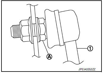
- To connect the stabilizer connecting rod (1), tighten the nut while holding the hexagonal part (A) on the stabilizer connecting rod.
- Perform the final tightening of the nuts and bolts under unladen conditions with the tires on level ground.
- Perform inspection after installation. Refer to FSU-6, "Inspection".
Inspection
INSPECTION AFTER REMOVAL
Check the stabilizer bar, the stabilizer connecting rod, the stabilizer bushing and the stabilizer clamp for deformation, cracks or damage. Replace components if necessary.
INSPECTION AFTER INSTALLATION
- Check the wheel alignment. Refer to FSU-7, "Inspection".
- Perform the steering angle sensor neutral position adjustment. Refer to BRC-70, "Work Procedure".
STEERING KNUCKLE
Exploded View
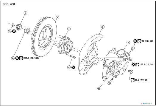
- Disc brake rotor
- Nut retainer
- Cotter pin
- Wheel stud
- Steering knuckle
- Splash guard
- Wheel hub and bearing
- Wheel hub lock nut
Removal and Installation
REMOVAL
- Remove the wheel and tire using power tool. Refer to WT-60, "Removal and Installation".
- Remove the bolt and separate the front wheel sensor from the steering knuckle. Separate the harness from the brackets and position aside. Refer to BRC-132, "FRONT WHEEL SENSOR : Exploded View".
CAUTION:
- Failure to separate the front wheel sensor from the steering knuckle may result in damage to the front wheel sensor.
- Pull out the front wheel sensor, being careful to turn it as little as possible. Do not pull on wheel sensor harness.
- Remove torque member bolts, leaving the brake hose
attached. Position brake caliper aside with wire.
Refer to BR-35, "BRAKE CALIPER ASSEMBLY (1 PISTON TYPE) : Exploded View" (1 PISTON TYPE), or BR-39, "BRAKE CALIPER ASSEMBLY (2 PISTON TYPE) : Exploded View" (2 PISTON TYPE).
- Put alignment marks on the disc brake rotor and on the wheel hub
and bearing. Remove the disc brake
rotor.
CAUTION: Do not drop the disc brake rotor.
- Remove the cotter pin from the drive shaft.
- Remove the nut retainer from the wheel hub lock nut.
- Loosen the wheel hub lock nut using power tool.
- Tap wheel hub lock nut with a piece of wood to disengage wheel
hub and bearing from drive shaft.
NOTE: Use a suitable puller if wheel hub and bearing and drive shaft cannot be separated even after performing the above procedure.
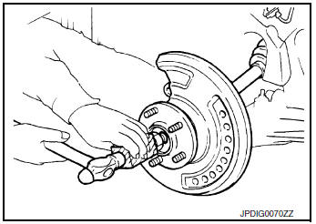
- Remove the wheel hub lock nut.
- Remove the nut and separate the stabilizer connecting rod from the strut bracket.
- Remove the nut, and separate the outer socket from the steering knuckle.
- Remove engine side undercover.
- Remove the lower nut and bolt from the steering knuckle. Separate the transverse link from the steering knuckle. Refer to FSU-17, "Exploded View".
- Separate drive shaft from wheel hub and bearing.
- Remove the bolts and the wheel hub and bearing and splash guard from the steering knuckle.
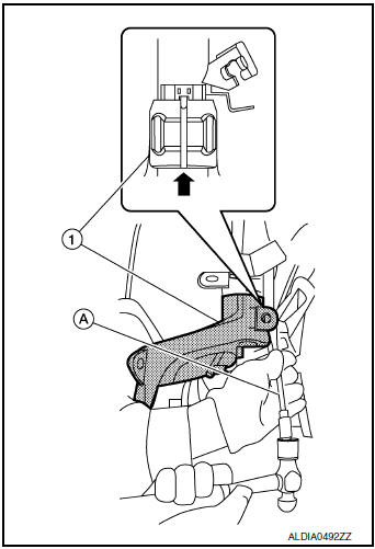
- Remove the upper nut and bolt from the steering knuckle.
- Open the slot using a suitable tool (A). Separate the steering knuckle (1) from the front coil spring and strut.
CAUTION: Do not drop steering knuckle.
- Inspect the components. Refer to FSU-6, "Inspection".
INSPECTION AFTER REMOVAL
Check for deformity, cracks and damage on each part, replace if necessary.
Ball Joint Inspection
- Check for boot breakage, axial looseness, and torque of transverse link ball joint and repair as necessary.
INSTALLATION
Installation is in the reverse order of removal.
CAUTION:
- Do not reuse the wheel hub lock nut.
- Do not reuse the cotter pin.
- Do not reuse steering knuckle upper bolt.
- Do not reuse steering knuckle lower nut.
- Check the wheel alignment. Refer to FSU-7, "Inspection".
- Adjust the neutral position of the steering angle sensor. Refer to BRC-70, "Work Procedure".
 Periodic maintenance
FRONT SUSPENSION ASSEMBLY
Inspection
COMPONENT
Check the conditions (looseness, backlash) of each component. Verify the
component conditions (wear, damage)
are normal.
Ball Joint Axial End Play ...
 Unit removal and installation
FRONT SUSPENSION MEMBER
Exploded View
Front suspension member
Strut mounting bearing
Rebound stopper insulator
Rebound stopper
Removal and Installation
REMOVAL
&nb ...
Other materials:
Precaution
Precaution for supplemental restraint system (srs) "air bag" and "seat
belt
pre-tensioner"
The Supplemental Restraint System such as ÔÇťAIR BAGÔÇŁ and ÔÇťSEAT BELT PRE-TENSIONERÔÇŁ,
used along
with a front seat belt, helps to reduce the risk or severity of injury to the
...
Precaution
Precaution for Supplemental Restraint System (SRS) "AIR BAG" and "SEAT
BELT
PRE-TENSIONER"
The Supplemental Restraint System such as ÔÇťAIR BAGÔÇŁ and ÔÇťSEAT BELT PRE-TENSIONERÔÇŁ,
used along
with a front seat belt, helps to reduce the risk or severity of injury to the
...
System
METER SYSTEM
METER SYSTEM : System Description
SYSTEM DIAGRAM
Combination Meter Input Signal (CAN Communication Signal)
DESCRIPTION
Combination Meter
The combination meter controls the following items according to
the signals received from each unit via CAN
communicat ...
