Nissan Rogue Service Manual: Front wiper auto stop signal circuit
Component Function Check
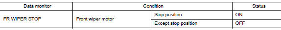
1. CHECK FRONT WIPER (AUTO STOP) SIGNAL
- Select FR WIPER STOP of BCM (WIPER) data monitor item.
- Operate the front wiper.
- Check that FR WIPER STOP changes from ON to OFF according to the wiper position
Is the inspection result normal? YES >> Front wiper auto stop signal circuit is normal.
NO >> Refer to WW-40, "Diagnosis Procedure".
Diagnosis Procedure
Regarding Wiring Diagram information, refer to WW-22, "Wiring Diagram".
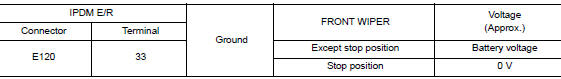
1. CHECK FRONT WIPER MOTOR (AUTO STOP) OUTPUT VOLTAGE
- Turn the ignition switch ON.
- Check voltage between IPDM E/R harness connector and ground.
Is the inspection result normal? YES >> Check for intermittent failure.
NO >> GO TO 2.
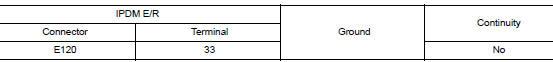
2. CHECK FRONT WIPER MOTOR (AUTO STOP) SHORT CIRCUIT
- Turn the ignition switch OFF.
- Disconnect IPDM E/R and front wiper motor.
- Check continuity between IPDM E/R harness connector and ground.
Is the inspection result normal? YES >> Repair or replace harness.
NO >> GO TO 3.
3. CHECK FRONT WIPER MOTOR (AUTO STOP) CIRCUIT CONTINUITY
Check continuity between IPDM E/R harness connector and front wiper motor harness connector.
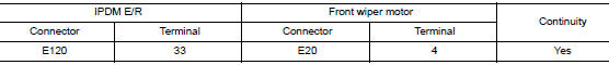
Is the inspection result normal?
YES >> Replace front wiper motor. Refer to WW-67, "Removal and Installation".
NO >> Repair or replace harness.
 Front wiper motor HI circuit
Component Function Check
1.CHECK FRONT WIPER HI OPERATION
CONSULT ACTIVE TEST
Select FR WIPER of BCM (WIPER) active test item.
Check front wiper operation.
HI : Front wiper (HI ...
 Front wiper motor ground circuit
Diagnosis Procedure
Regarding Wiring Diagram information, refer to WW-22, "Wiring Diagram".
1. CHECK FRONT WIPER MOTOR GROUND CIRCUIT
Turn the ignition switch OFF.
Discon ...
Other materials:
Unit removal and installation
FRONT SUSPENSION MEMBER
Exploded View
Front suspension member
Strut mounting bearing
Rebound stopper insulator
Rebound stopper
Removal and Installation
REMOVAL
Remove the wheel and tire using power tool. Refer to WT-60,
"Removal and Installation&quo ...
Precaution
Precaution for supplemental restraint system (srs) "air bag" and "seat
belt
pre-tensioner"
The Supplemental Restraint System such as “AIR BAG” and “SEAT BELT PRE-TENSIONER”,
used along
with a front seat belt, helps to reduce the risk or severity of injury to the
...
Checking engine oil level
Checking engine oil level
Park the vehicle on a level surface and apply
the parking brake.
Start the engine and let it idle until it reaches
operating temperature.
Turn off the engine. Wait more than
10 minutes for the oil to drain back into
the oil pan.
Remov ...
