Nissan Rogue Service Manual: Rear shock absorber
Exploded View
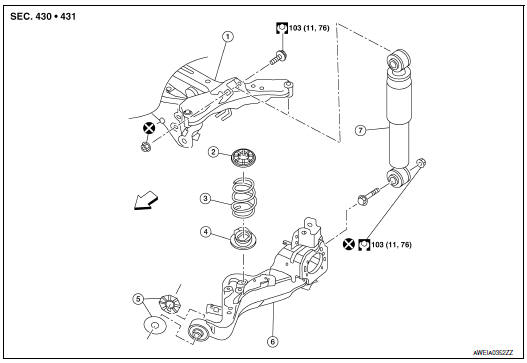
- Rear suspension member
- Upper seat
- Coil spring
- Lower seat
- Rubber washer (LH/RH)
- Rear suspension arm
- Rear shock absorber
 Front
Front
Removal and Installation
REMOVAL
- Support the rear suspension arm using a suitable jack.
CAUTION: Do not damage the rear suspension arm with the suitable jack.
- Remove the lower shock absorber bolt and nut. Separate the shock absorber from the rear suspension arm.
- Remove the upper bolt, nut, and shock absorber.
- Inspect the components. Refer to RSU-5, "Inspection and Adjustment".
INSTALLATION
Installation is in the reverse order of removal.
CAUTION: Do not reuse the lower shock absorber nut.
- Perform the final tightening of nuts and bolts under unladen conditions with tires on level ground.
Inspection
INSPECTION AFTER REMOVAL
- Check shock absorber for deformation, cracks, damage. Replace it if necessary.
- Check welded and sealed areas for oil leaks. Replace it if necessary.
Disposal
- Set shock absorber horizontally to the ground with the piston rod fully extracted.
- Drill 2 – 3 mm (0.08 – 0.12 in) hole at the position (
 ) from top
as shown in the figure to release gas gradually.
) from top
as shown in the figure to release gas gradually.
CAUTION:
- Wear eye protection (safety glasses).
- Wear gloves.
- Be careful with metal chips or oil blown out by the compressed gas.
NOTE:
- Drill vertically in this direction (
 ) directly into the outer tube
avoiding brackets.
) directly into the outer tube
avoiding brackets. - The gas is clear, colorless, odorless, and harmless.
A: 20 – 30 mm (0.79 – 1.18 in)
- Position the drilled hole downward and drain oil by moving the piston rod several times.
CAUTION: Dispose of drained oil according to the law and local regulations.
 Coil spring
Exploded View
Upper seat
Coil spring
Lower seat
Rubber washer (LH/RH)
Rear suspension arm
Front
Removal and Installation - FWD
REMOVAL
Remove the rear wh ...
 Rear suspension ARM
Exploded View
Rear suspension arm
Rubber washer (LH/RH)
Rear suspension arm bracket
Rear suspension arm stay
Front
Removal and Installation
REMOVAL
Remove the wheel hu ...
Other materials:
Brake booster
Inspection
Operation
Depress the brake pedal several times at five second intervals with
the engine stopped. Start the engine with the brake pedal fully
depressed. Check that the clearance between brake pedal and dash
lower panel decreases.
NOTE:
A slight impact with a small click may be fe ...
Precautions when starting and driving
WARNING
Do not leave children or adults who
would normally require the assistance
of others alone in your vehicle. Pets
should also not be left alone. They
could accidentally injure themselves or
others through inadvertent operation of
the vehicle. Also, on h ...
Normal operating condition
Description
Symptom
Result
Brake pedal slightly vibrates and operation sound (motor sound and
sound from suspension)
occurs when VDC function, TCS function, ABS function, EBD function,
Brake limited
slip differential (BLSD) function, Brake assist function, hill ...
