Nissan Rogue Service Manual: Coil spring
Exploded View
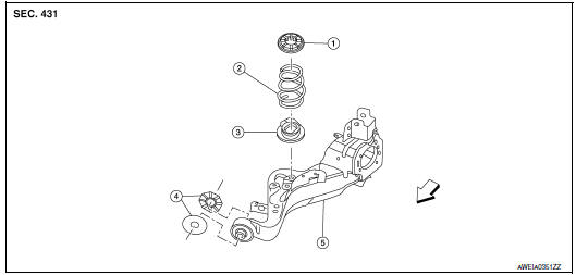
- Upper seat
- Coil spring
- Lower seat
- Rubber washer (LH/RH)
- Rear suspension arm
 Front
Front
Removal and Installation - FWD
REMOVAL
- Remove the rear wheel and tire using power tool.
- Remove the bolt and separate the rear wheel sensor from the wheel hub and bearing. Refer to BRC-133, "REAR WHEEL SENSOR : Exploded View".
CAUTION:
- Failure to separate the rear wheel sensor from the wheel hub and bearing may result in damage to the rear wheel sensor.
- Pull out the rear wheel sensor, being careful to turn it as little as possible. Do not pull on wheel sensor harness.
- Remove torque member bolts, leaving the brake hose attached.
Position brake caliper aside with wire.
Refer to BR-42, "BRAKE CALIPER ASSEMBLY : Exploded View".
CAUTION: Do not depress brake pedal while brake caliper is removed.
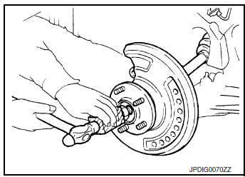
- Put alignment marks on the disc brake rotor and on wheel hub and
bearing. Remove the disc brake rotor.
CAUTION: Do not drop the disc brake rotor.
- Support the rear suspension arm using a suitable jack.
CAUTION: Do not damage the rear suspension arm with the suitable jack.
- Remove the stabilizer connecting rod. Refer to RSU-17, "Exploded View".
- Separate the parking brake cable from the rear suspension arm. Refer to PB-7, "Exploded View".
- Remove the rear height sensor (if equipped). Refer to EXL-271, "Removal and Installation - Rear Height Sensor".
- Remove the rear shock absorber lower bolt and nut. Separate the rear shock absorber from the rear suspension arm. Refer to RSU-8, "Exploded View".
- Remove the upper link bolt and nut from the rear suspension arm. Separate the upper link from the rear suspension arm. Refer to RSU-16, "Exploded View".
- Loosen the lower link nut at the rear suspension member. Remove the lower link bolt and nut from the rear suspension arm. Separate the lower link from the rear suspension arm. Refer to RSU-16, "Exploded View".
- Separate the brake tube from the rear suspension arm. Refer to BR-24, "REAR : Exploded View".
- Slowly lower the suitable jack supporting the rear suspension arm. Remove the upper seat, the coil spring and the lower seat.
INSTALLATION
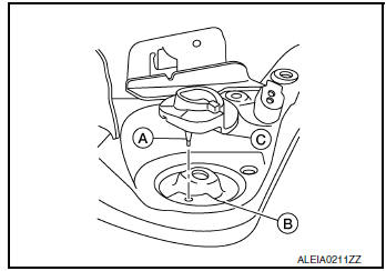
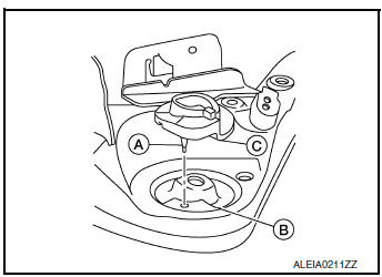
- Align the lower seat indentations (C) with rear suspension arm grooves (B). Install the lower seat protrusion (A) into the hole in the rear suspension arm.
CAUTION: The lower rubber seat protrusion must be securely inserted into the hole of rear suspension arm.
- Identify the upper side of the coil spring.
NOTE:
- The top of the coil spring has a flat shape.
- The paint identification mark (A) is 1.75 turns from the bottom of the coil spring.
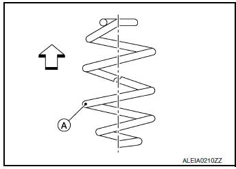
: Upper side
- Align the coil spring (1) to the lower seat (2). Install coil spring to lower seat.
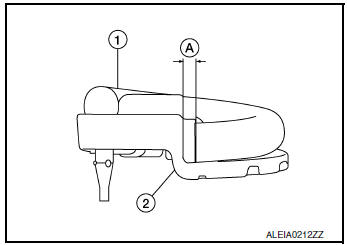
Maximum distance (A) : 5mm (0.20 in)
CAUTION: Assemble coil spring so that spring lower end is located in the spring end holding section of lower rubber seat.
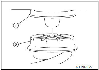
- Align upper seat (2) to the body (1). Slowly raise the suitable jack supporting the rear suspension arm to install the upper seat to the body.
- Install brake tube to rear suspension arm. Refer to BR-24, "REAR : Exploded View".
- Install lower link with bolt and nut to the rear suspension arm. Refer
to RSU-16, "Exploded View".
NOTE: The final tightening of nuts and bolts is under unladen conditions with tires on level ground.
- Install upper link with bolt and nut to rear suspension arm. Refer to RSU-16, "Exploded View".
- Install rear shock absorber with bolt and nut to rear suspension arm. Refer to RSU-8, "Exploded View".
- Install height sensor (if equipped) to rear suspension arm. Refer to EXL-271, "Removal and Installation - Rear Height Sensor".
- Install parking brake cable to rear suspension arm. Refer to PB-7, "Exploded View".
- Install the stabilizer connecting rod. Refer to EXL-271, "Removal and Installation - Rear Height Sensor".
- Install the rear wheel sensor to the axle housing. Refer to BRC-133, "REAR WHEEL SENSOR : Exploded View".
CAUTION:
- Before installing, make sure there is no foreign material such as iron fragments adhered to the pick-up part of the rear wheel sensor.
- When installing, make sure there is no foreign material such as iron fragments on and in the hole in the wheel hub and bearing for the rear wheel sensor. Make sure no foreign material has been caught in the sensor rotor. Remove and foreign material and clean the mount.
- Align the matching marks on the disc brake rotor and on the wheel hub and bearing. Install the disc brake rotor.
- Install the brake caliper and the torque member bolts. Refer to BR-42, "BRAKE CALIPER ASSEMBLY : Exploded View".
- Install the wheel and tire. Refer to WT-60, "Removal and Installation".
- Perform the final tightening of nuts and bolts under unladen conditions with tires on level ground.
- Perform the inspection after installation. Refer to RSU-13, "Inspection".
Removal and Installation - AWD
REMOVAL
- Remove wheel and tire using power tool.
- Remove the rbolt and seperate the rear wheel sensor from the axle housing. Position the rear wheel sensor and harness aside. Refer to BRC-133, "REAR WHEEL SENSOR : Exploded View".
CAUTION:
- Failure to remove the rear speed sensor from the axle housing may result in damage to the rear wheel sensor.
- Pull out the rear wheel sensor, being careful to turn it as little as possible. Do not pull on wheel sensor harness.
- Remove torque member bolts using power tool, leaving the brake hose
attached. Position brake caliper
aside with wire. Refer to BRC-133, "REAR WHEEL SENSOR : Exploded View".
CAUTION: Do not depress brake pedal while brake caliper is removed.
- Put alignment marks on the disc brake rotor and on the wheel hub and
bearing. Remove the disc brake
rotor.
CAUTION: Do not drop disc brake rotor.
- Remove the cotter pin.
- Loosen, but do not remove, the wheel hub and bearing lock nut from the drive shaft using power tool.
- Tap the wheel hub and bearing lock nut with a piece of wood to disengage the drive shaft from the wheel hub and bearing.
CAUTION:
- Do not place the drive shaft joint at an extreme angle. Be careful not to overextend the slide joint.
- Do not allow the drive shaft to hang without support.
NOTE: Use a suitable puller if the drive shaft cannot be separated from the wheel hub and bearing.
- Remove the wheel hub and bearing lock nut.
- Support the rear suspension arm using a suitable jack.
CAUTION: Do not damage the rear suspension arm with suitable jack.
- Remove stabilizer connecting rod. Refer to RSU-21, "Exploded View".
- Separate the parking brake cable from the rear suspension arm. Refer to PB-7, "Exploded View".
- Remove the height sensor (if equipped). Refer to EXL-271, "Removal and Installation - Rear Height Sensor".
- Remove the rear shock absorber lower bolt and nut. Separate the rear shock absorber from the rear suspension arm. Refer to RSU-14, "Exploded View".
- Remove the upper link bolt and nut from the rear suspension arm. separate the upper link from the rear suspension arm. Refer to RSU-19, "Exploded View".
- Loosen the lower link nut at the rear suspension member. Remove the lower link bolt and nut from the rear suspension arm. Separate the lower link from the rear suspension arm. Refer to RSU-17, "Exploded View".
- Separate the brake tube from the rear suspension arm. Refer to BR-24, "REAR : Exploded View".
- Slowly lower the suitable jack supporting the suspension arm. Remove the upper seat, coil spring and lower seat.
INSTALLATION
- Align the lower seat indentations (C) with rear suspension arm
grooves (B). Install the lower seat protusion (A) into the hole in
the suspension arm.
CAUTION: The lower rubber seat protrusion must be securely inserted into the hole of rear suspension arm.
- Identify the upper side of the coil spring.
NOTE:
- The top of the coil spring has a flat shape.
- The paint identification mark (A) is 1.75 turns from the bottom of the coil spring.
 : Upper side
- Align the coil spring (1) to the lower seat (2). Install coil spring to lower seat.
Maximum distance (A) : 5mm (0.20 in)
CAUTION: Assemble coil spring so that spring lower end is located in the spring end holding section of lower rubber seat.
- Align the coil spring (1) to the upper seat (2). Install the upper seat to the coil spring.
- Align upper seat (2) to the body (1). Slowly raise the suitable jack supporting the rear suspension arm to install the upper seat to the body.
- Install the brake tube to the rear suspension arm. Refer to BR-24, "REAR : Exploded View".
- Install the lower link with the bolt and nut to the rear suspension arm.
Refer to RSU-16, "Exploded View".
NOTE: The final tightening of nuts and bolts is under unladen conditions with tires on level ground.
- Install the upper link with the bolt and nut to the rear suspension arm. Refer to RSU-16, "Exploded View".
- Install the rear shock absorber with the bolt and nut to the rear suspension arm. Refer to RSU-8, "Exploded View".
- Install the height sensor (if equipped) to the rear suspension arm. Refer to EXL-271, "Removal and Installation - Rear Height Sensor".
- Install parking brake cable to rear suspension arm. Refer to PB-7, "Exploded View".
- Install the stabilizer connecting rod. Refer to EXL-271, "Removal and Installation - Rear Height Sensor".
- Install the rear wheel sensor to the axle housing. Refer to BRC-133, "REAR WHEEL SENSOR : Exploded View".
CAUTION:
- Before installing, make sure there is no foreign material such as iron fragments adhered to the pick-up part of the rear wheel sensor.
- When installing, make sure there is no foreign material such as iron fragments on and in the hole in the axle housing for the rear wheel sensor. Make sure no foreign material has been caught in the sensor rotor. Remove and foreign material and clean the mount.
- Align the matching marks on the disc brake rotor and on the wheel hub and bearing. Install the disc brake rotor.
- Install the brake caliper and the torque member bolts. Refer to BR-42, "BRAKE CALIPER ASSEMBLY : Exploded View".
- Install the wheel and tire. Refer to WT-60, "Removal and Installation".
- Perform the final tightening of nuts and bolts under unladen conditions with tires on level ground.
- Perform the inspection after installation. Refer to RSU-13, "Inspection".
Inspection
INSPECTION AFTER REMOVAL
Check lower link, bushing and coil spring for deformation, crack, and damage. Replace components if necessary.
INSPECTION AFTER INSTALLATION
- Check wheel alignment. Refer to RSU-6, "Inspection".
- Adjust the neutral position of the steering angle sensor. Refer to BRC-70, "Work Procedure".
- Initialize the headlamp level control unit. Refer to EXL-115, "Aiming Adjustment Procedure" (HALOGEN HEADLAMP) or EXL-264, "Aiming Adjustment Procedure" (LED HEADLAMP).

 Rear shock absorber
Exploded View
Rear suspension member
Upper seat
Coil spring
Lower seat
Rubber washer (LH/RH)
Rear suspension arm
Rear shock absorber
Front
Removal and Installation
REMOVAL ...
Other materials:
Heater and Air Conditioner (manual)
(if so equipped)
Heater and Air Conditioner
Fan speed control / system OFF dial / air
conditioning (A/C) button
Air flow control
buttons
Temperature control dial / MAX A/C button
Air recirculation button
Rear window and
outside mirror (if so
equipped) defroster but ...
Preparation
Special Service Tool
The actual shape of the tools may differ from those illustrated here.
Tool number
(TechMate No.)
Tool name
Description
ŌĆö
(165-GR8-1200KIT-NI)
Multitasking battery and electrical diagnostic
station
Testing batteries, starti ...
Engine oil and oil filter recommendations
Selecting the correct oil
It is essential to choose the correct grade, quality
and viscosity engine oil to ensure satisfactory
engine life and performance. Refer to ŌĆ£Recommended
fluids/lubricants and capacitiesŌĆØ in this
section. NISSAN recommends the use of an
energy conserving oil in ...
