Nissan Rogue Service Manual: Symptom diagnosis
HEATER AND AIR CONDITIONING SYSTEM CONTROL SYMPTOMS
Diagnosis Chart By Symptom
NOTE: Perform the self-diagnoses with CONSULT before performing the symptom diagnosis. If DTC is detected, perform the corresponding diagnosis.
|
Symptom |
Corresponding malfunction part |
Reference |
|
|
|
HAC-56, "Diagnosis Procedure" | |
|
|
HAC-80, "Diagnosis Procedure" | |
|
|
HAC-67, "Diagnosis Procedure" | |
|
|
HAC-70, "Diagnosis Procedure" | |
|
|
HAC-77, "Diagnosis Procedure" | |
| Blower motor operation is malfunctioning. |
|
HAC-85, "Diagnosis Procedure" | |
| Compressor does not operate. |
|
HAC-91, "Diagnosis Procedure" | |
|
|
HAC-98, "Diagnosis Procedure" | |
|
|
HAC-99, "Diagnosis Procedure" | |
| Noise is heard when front air conditioning system operates. | During compressor operation | Refrigerant cycle | HA-20, "Symptom Table" |
| During front blower motor operation |
|
HAC-88, "Component Inspection (Front Blower Motor)" | |
|
|
HAC-56, "Diagnosis Procedure" | |
INSUFFICIENT COOLING
Description
Symptom
- Insufficient cooling
- No cool air comes out. (Air flow volume is normal.)
Diagnosis Procedure
NOTE: Perform self-diagnoses with CONSULT before performing symptom diagnosis. If any DTC is detected, perform the corresponding diagnosis.
1.CHECK MAGNET CLUTCH OPERATION
- Turn ignition switch ON.
- Operate fan switch.
- Press A/C switch.
- Check that A/C indicator turns ON. Check visually and by sound that compressor operates.
- Press A/C switch again.
- Check that A/C indicator turns OFF. Check that compressor stops.
Is the inspection result normal? YES >> GO TO 2.
NO >> Perform diagnosis of ŌĆ£COMPRESSOR DOES NOT OPERATEŌĆØ in ŌĆ£SYMPTOM DIAGNOSISŌĆØ.
Refer to HAC-100, "Diagnosis Procedure".
2.CHECK DRIVE BELT
Check tension of drive belt. Refer to EM-13, "Checking".
Is the inspection result normal? YES >> GO TO 3.
NO >> Adjust or replace drive belt depending on the inspection results.
3.CHECK REFRIGERANT CYCLE
Connect recovery/recycling recharging equipment to the vehicle and perform pressure inspection with gauge.
Refer to HA-17, "Symptom Table".
Is the inspection result normal? YES >> GO TO 4.
NO >> Repair or replace parts depending on the inspection results.
4.CHECK AIR LEAKAGE FROM EACH DUCT
Check duct and nozzle, etc. of the front air conditioning system for leakage.
Is the inspection result normal? YES >> GO TO 5.
NO >> Repair or replace parts depending on the inspection results.
5.CHECK SETTING OF TEMPERATURE SETTING TRIMMER (FRONT)
- Check setting value of temperature setting trimmer (front). Refer to HAC-50, "Temperature Setting Trimmer".
- Check that temperature setting trimmer (front) is set to ŌĆ£+ directionŌĆØ.
NOTE: The control temperature can be set with the setting of the temperature setting trimmer (front).
- Set difference between set temperature and control temperature to ŌĆ£0ŌĆØ.
Is inspection result normal? YES >> Inspection End.
NO >> Replace A/C auto amp. Refer to HAC-103, "Removal and Installation".
INSUFFICIENT HEATING
Description
Symptom
- Insufficient heating
- No warm air comes out. (Air flow volume is normal.)
Diagnosis Procedure
NOTE: Perform self-diagnosis with CONSULT before performing symptom diagnosis. If DTC is detected, perform the corresponding diagnosis.
1.CHECK COOLING SYSTEM
- Check engine coolant level and check leakage. Refer to CO-8, "Inspection".
- Check reservoir tank cap. Refer to CO-12, "RADIATOR CAP : Inspection".
- Check water flow sounds of the engine coolant. Refer to CO-8, "Inspection".
Is the inspection result normal? YES >> GO TO 2.
NO >> Refill engine coolant and repair or replace parts depending on the inspection results.
2.CHECK HEATER HOSE
Check installation of heater hose visually or by touching.
Is the inspection result normal? YES >> GO TO 3.
NO >> Repair or replace parts depending on the inspection results.
3.CHECK HEATER CORE
- Check temperature of inlet hose and outlet hose of front heater core.
- Check that inlet side of heater core is hot and the outlet side is slightly lower than/almost equal to the inlet side.
CAUTION: Always perform the temperature inspection in a short period of time because the engine coolant temperature is very hot. Is the inspection result normal? YES >> GO TO 4.
NO >> Replace heater core. Refer to HA-43, "HEATER CORE : Removal and Installation".
4.CHECK AIR LEAKAGE FROM EACH DUCT
Check duct and nozzle, etc. of front air conditioning system for air leakage.
Is the inspection result normal? YES >> GO TO 5.
NO >> Repair or replace parts depending on the inspection results.
5.CHECK SETTING OF TEMPERATURE SETTING TRIMMER (FRONT)
- Check setting value of temperature setting trimmer (front). Refer to HAC-50, "Temperature Setting Trimmer".
- Check that temperature setting trimmer (front) is set to ŌĆ£ŌłÆ
directionŌĆØ.
NOTE: The control temperature can be set by the temperature setting trimmer (front).
- Set difference between the set temperature and control temperature to ŌĆ£0ŌĆØ.
Are the symptoms solved? YES >> Inspection End.
NO >> Replace A/C auto amp. Refer to HAC-103, "Removal and Installation".
COMPRESSOR DOES NOT OPERATE
Description
Symptom: Compressor does not operate.
Diagnosis Procedure
NOTE:
- Perform self-diagnoses with CONSULT before performing symptom diagnosis. If DTC is detected, perform the corresponding diagnosis.
- Check that refrigerant system is properly charged. If refrigerant amount is below the proper amount, perform inspection of refrigerant leakage.
1.CHECK MAGNET CLUTCH OPERATION
Check magnet clutch. Refer to HAC-91, "Component Function Check".
Does it operate normally? YES >> GO TO 2.
NO >> Repair or replace malfunctioning parts.
2.CHECK REFRIGERANT PRESSURE SENSOR
Check refrigerant pressure sensor. Refer to EC-482, "Component Function Check".
Is the inspection result normal? YES >> GO TO 3.
NO >> Repair or replace malfunctioning parts.
3.CHECK A/C AUTO AMP. OUTPUT SIGNAL
 With CONSULT
Check ŌĆ£COMP REQ SIGŌĆØ and ŌĆ£FAN REQ SIGŌĆØ in ŌĆ£DATA MONITORŌĆØ mode of ŌĆ£HVACŌĆØ using CONSULT.
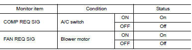
Is the inspection result normal? YES >> GO TO 4.
NO >> Replace A/C auto amp. Refer to HAC-103, "Removal and Installation".
4.CHECK ECM INPUT SIGNAL
With CONSULT
Check ŌĆ£AIR COND SIGŌĆØ and ŌĆ£HEATER FAN SWŌĆØ in ŌĆ£DATA MONITORŌĆØ mode of ŌĆ£ECMŌĆØ using CONSULT.
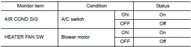
Is the inspection result normal? YES >> GO TO 5.
NO >> Check CAN communication system. Refer to LAN-17, "Trouble Diagnosis Flow Chart".
5.CHECK IPDM E/R INPUT SIGNAL
With CONSULT
- Start engine.
- Check ŌĆ£AC COMP REQŌĆØ in ŌĆ£DATA MONITORŌĆØ mode of ŌĆ£IPDM E/RŌĆØ using CONSULT.
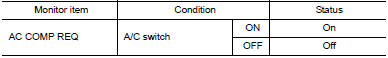
Is the inspection result normal? YES >> Inspection End.
NO >> Check CAN communication system. Refer to LAN-17, "Trouble Diagnosis Flow Chart".
 DTC/circuit diagnosis
U1000 CAN COMM CIRCUIT
Description
CAN (Controller Area Network) is a serial communication system for real time
application. It is an on-vehicle
multiplex communication system with high data comm ...
 Removal and installation
A/C SWITCH ASSEMBLY
Removal and Installation
REMOVAL
Release the A/C switch assembly clips and pawls using a suitable
tool.
: Metal clip
: Pawl
Disconnect the harness con ...
Other materials:
Preparation
Special Service Tool
The actual shape of the tools may differ from those illustrated here.
Tool number
(TechMate No.)
Tool name
Description
ŌĆö
(J-46534)
Trim Tool Set
Removing trim components
Commercial Service Tools
Tool name
...
Front disc brake
BRAKE PAD
BRAKE PAD : Inspection
Check brake pad wear thickness from an inspection hole (A) on cylinder
body. Check using a scale if necessary.
Wear thickness : Refer to BR-55, "Front Disc Brake".
DISC BRAKE ROTOR
DISC BRAKE ROTOR : Inspection
APPEARANCE
Check surface of disc b ...
P0453 EVAP control system pressure sensor
DTC Description
DTC DETECTION LOGIC
DTC No.
CONSULT screen terms
(Trouble diagnosis content)
DTC detecting condition
P0453
EVAP SYS PRES SEN
(Evaporative emission system pressure
sensor/switch high)
An excessively high voltage from the sensor is sent to ECM.
...
