Nissan Rogue Service Manual: DTC/circuit diagnosis
U1000 CAN COMM CIRCUIT
Description
CAN (Controller Area Network) is a serial communication system for real time application. It is an on-vehicle multiplex communication system with high data communication speed and excellent error detection ability.
Many electronic control units are equipped onto vehicles, and each control unit shares information and links with other control units during operation (not independent). In CAN communication, control units are connected with two communication lines (CAN-H line, CAN-L line) allowing a high rate of information transmission with less wiring. Each control unit transmits/receives data but selectively reads required data only. Refer to LAN-32, "CAN COMMUNICATION SYSTEM : CAN Communication Signal Chart".
DTC Logic
DTC DETECTION LOGIC
| DTC | Items (CONSULT screen terms) | DTC detection condition | Possible cause |
| U1000 | CAN COMM CIRCUI | When A/C auto amp. is not transmitting or receiving CAN communication signal for 2 or more seconds. | CAN communication system |
DTC CONFIRMATION PROCEDURE
1.PERFORM SELF-DIAGNOSIS
 With CONSULT
- Turn ignition switch ON and wait for 2 seconds or more.
- Using CONSULT, perform “Self Diagnostic Result” of “HVAC”.
- Check if any DTC No. is displayed in the self-diagnosis results.
Is DTC detected? YES >> Refer to HAC-53, "Diagnosis Procedure".
NO >> Refer to GI-41, "Intermittent Incident".
Diagnosis Procedure
1.CHECK CAN COMMUNICATION SYSTEM
Check CAN communication system. Refer to LAN-17, "Trouble Diagnosis Flow Chart".
>> Inspection End.
U1010 CONTROL UNIT (CAN)
Description
Initial diagnosis of A/C auto amp.
DTC Logic
DTC DETECTION LOGIC
| DTC | Items (CONSULT screen terms) | DTC detection condition | Possible cause |
| U1010 | CONTROL UNIT (CAN) | When detecting error during the initial diagnosis of CAN controller of A/C auto amp. | A/C auto amp. |
DTC CONFIRMATION PROCEDURE
1.PERFORM SELF-DIAGNOSIS
With CONSULT
- Turn ignition switch ON.
- Using CONSULT, perform “Self Diagnostic Result” of “HVAC”.
- Check if any DTC No. is displayed in the self-diagnosis results.
Is DTC detected? YES >> Refer to HAC-54, "Diagnosis Procedure".
NO >> Inspection End.
Diagnosis Procedure
NOTE: This DTC can be set if the BCM is placed in transit mode. Confirm if the DTC is CURRENT or PAST. If PAST, perform the following steps before carrying out Diagnosis Procedure.
- Clear DTC using CONSULT. Refer to HAC-22, "CONSULT Function (HVAC)".
- Perform OPERATION INSPECTION. Refer to HAC-48, "Work Procedure".
- Perform “Self Diagnostic Result” of “HVAC” using CONSULT. Refer to HAC-22, "CONSULT Function (HVAC)".
- If DTC resets, proceed with Diagnosis Procedure.
1.REPLACE A/C AUTO AMP.
Replace A/C auto amp. Refer to HAC-103, "Removal and Installation".
>> Inspection End.
B24A0 A/C AUTO AMP.
DTC Logic
DTC DETECTION LOGIC
NOTE:
- If DTC is displayed along with DTC U1000, first perform the trouble diagnosis for DTC U1000. Refer to HAC- 53, "DTC Logic".
- If DTC is displayed along with DTC U1010, first perform the trouble diagnosis for DTC U1010. Refer to HAC- 54, "DTC Logic".
| DTC | Items (CONSULT screen terms) | DTC detection condition | Possible cause |
| B24A0 | A/C AUTO AMP. | A/C auto amp. EEPROM system is malfunctioning. | A/C auto amp. |
DTC CONFIRMATION PROCEDURE
1.PERFORM DTC CONFIRMATION PROCEDURE
With CONSULT
- Turn ignition switch ON.
- Using CONSULT, perform “Self Diagnostic Result” of “HVAC”.
- Check if any DTC No. is displayed in the self-diagnosis results.
Is DTC detected? YES >> Refer to HAC-55, "Diagnosis Procedure".
NO >> Inspection End.
Diagnosis Procedure
1.PERFORM SELF DIAGNOSTIC
With CONSULT
- Turn ignition switch ON.
- Select “Self Diagnostic Result” mode of “HVAC” using CONSULT.
- Touch “ERASE”.
- Turn ignition switch OFF.
- Turn ignition switch ON.
- Perform “DTC CONFIRMATION PROCEDURE”. Refer to HAC-55, "DTC Logic".
Is DTC detected again? YES >> Replace A/C auto amp. Refer to HAC-103, "Removal and Installation".
NO >> Inspection End.
B24A1 A/C AUTO AMP. POWER SUPPLY
DTC Logic
DTC DETECTION LOGIC
| DTC | Items (CONSULT screen terms) | DTC detection condition | Possible cause |
| B24A1 | A/C AUTO AMP. POWER SUPPLY | A/C auto amp. power supply is out of range |
|
DTC CONFIRMATION PROCEDURE
1.PERFORM DTC CONFIRMATION PROCEDURE
With CONSULT
- Turn ignition switch ON.
- Using CONSULT, perform “Self Diagnostic Result” of “HVAC”.
- Check if any DTC No. is displayed in the self-diagnosis results.
Is DTC detected? YES >> Refer to HAC-56, "Diagnosis Procedure".
NO >> Inspection End.
Diagnosis Procedure
Regarding Wiring Diagram information, refer to HAC-35, "Wiring Diagram".
1.CHECK FUSE
Check 10A fuse [No. 20, located in the fuse block (J/B)].
NOTE: Refer to PG-64, "Terminal Arrangement".
Is the inspection result normal? YES >> GO TO 2.
NO >> Replace the blown fuse after repairing the affected circuit.
2.CHECK A/C AUTO AMP. POWER SUPPLY
- Turn ignition switch OFF.
- Disconnect A/C auto amp. connector.
- Check voltage between A/C auto amp. harness connector and ground.
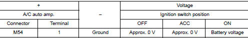
Is the inspection result normal? YES >> GO TO 3.
NO >> Repair harness or connector between A/C auto amp. and fuse block (J/B).
3.CHECK A/C AUTO AMP. GROUND CIRCUIT
- Turn ignition switch OFF.
- Check continuity between A/C auto amp. harness connector and ground.
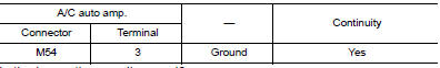
Is the inspection result normal? YES >> Inspection End.
NO >> Repair harness or connector.
B24A4 INTAKE SENSOR
DTC Logic
DTC DETECTION LOGIC
NOTE:
- If DTC is displayed along with DTC U1000, first perform the trouble diagnosis for DTC U1000. Refer to HAC- 53, "DTC Logic".
- If DTC is displayed along with DTC U1010, first perform the trouble diagnosis for DTC U1010. Refer to HAC- 54, "DTC Logic".
| DTC | Items (CONSULT screen terms) | DTC detection condition | Possible cause |
| B24A4 | INTAKE SENSOR | The intake sensor recognition temperature is too high. |
|
| The intake sensor recognition temperature is too low. |
DTC CONFIRMATION PROCEDURE
1.PERFORM DTC CONFIRMATION PROCEDURE
With CONSULT
- Turn ignition switch ON.
- Using CONSULT, perform “Self Diagnostic Result” of “HVAC”.
- Check if any DTC No. is displayed in the self-diagnosis results.
Is DTC detected? YES >> Refer to HAC-58, "Diagnosis Procedure".
NO >> Inspection End.
Diagnosis Procedure
Regarding Wiring Diagram information, refer to HAC-35, "Wiring Diagram".
1.CHECK INTAKE SENSOR POWER SUPPLY
- Turn ignition switch OFF.
- Disconnect intake sensor connector.
- Turn ignition switch ON.
- Check voltage between intake sensor harness connector and ground.
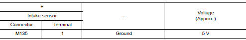
Is the inspection result normal? YES >> GO TO 2.
NO >> GO TO 4.
2.CHECK INTAKE SENSOR GROUND CIRCUIT
- Turn ignition switch OFF.
- Check continuity between intake sensor harness connector and ground.
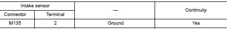
Is the inspection result normal? YES >> GO TO 3.
NO >> Repair harness or connector.
3.CHECK INTAKE SENSOR
Check intake sensor. Refer to HAC-59, "Component Inspection".
Is the inspection result normal? YES >> Replace A/C auto amp. Refer to HAC-103, "Removal and Installation".
NO >> Replace intake sensor. Refer to HAC-107, "Removal and Installation".
4.CHECK INTAKE SENSOR POWER SUPPLY CIRCUIT FOR OPEN
- Turn ignition switch OFF.
- Disconnect A/C auto amp. connector.
- Check continuity between intake sensor harness connector and A/C auto amp. harness connector.
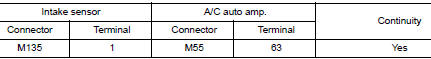
Is the inspection result normal? YES >> GO TO 5.
NO >> Repair harness or connector.
5.CHECK INTAKE SENSOR POWER SUPPLY CIRCUIT FOR SHORT TO GROUND
Check continuity between intake sensor harness connector and ground.
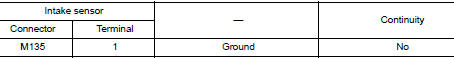
Is the inspection result normal? YES >> GO TO 6.
NO >> Repair harness or connector.
6.CHECK INTAKE SENSOR POWER SUPPLY CIRCUIT FOR SHORT TO VOLTAGE
- Turn ignition switch ON.
- Check voltage between intake sensor harness connector and ground.
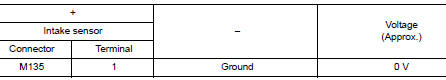
Is the inspection result normal? YES >> Replace A/C auto amp. Refer to HAC-103, "Removal and Installation".
NO >> Repair harness or connector.
Component Inspection
1.CHECK INTAKE SENSOR
- Turn ignition switch OFF.
- Disconnect intake sensor connector.
- Check resistance between intake sensor terminals.
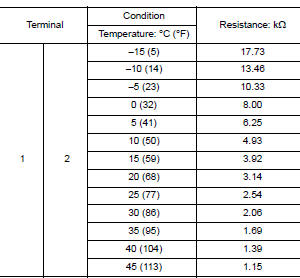
Is the inspection result normal? YES >> Inspection End.
NO >> Replace intake sensor. Refer to HAC-107, "Removal and Installation".
B24A6 IN-VEHICLE SENSOR
DTC Logic
DTC DETECTION LOGIC
NOTE:
- If DTC is displayed along with DTC U1000, first perform the trouble diagnosis for DTC U1000. Refer to HAC- 53, "DTC Logic".
- If DTC is displayed along with DTC U1010, first perform the trouble diagnosis for DTC U1010. Refer to HAC- 54, "DTC Logic".
| DTC | Items (CONSULT screen terms) | DTC detection condition | Possible cause |
| B24A6 | IN-VEHICLE SENSOR | The in-vehicle sensor recognition temperature is too high. |
|
| The in-vehicle sensor recognition temperature is too low. |
DTC CONFIRMATION PROCEDURE
1.PERFORM DTC CONFIRMATION PROCEDURE
 With CONSULT
- Turn ignition switch ON.
- Using CONSULT, perform “Self Diagnostic Result” of “HVAC”.
- Check if any DTC No. is displayed in the self-diagnosis results.
Is DTC detected? YES >> Refer to HAC-61, "Diagnosis Procedure".
NO >> Inspection End.
Diagnosis Procedure
Regarding Wiring Diagram information, refer to HAC-35, "Wiring Diagram".
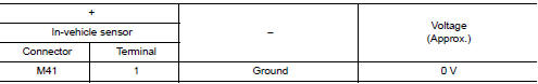
1.CHECK IN-VEHICLE SENSOR POWER SUPPLY
- Turn ignition switch OFF.
- Disconnect in-vehicle sensor connector.
- Turn ignition switch ON.
- Check voltage between in-vehicle sensor harness connector and ground.
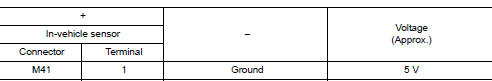
Is the inspection result normal? YES >> GO TO 2.
NO >> GO TO 4.
2.CHECK CONTINUITY BETWEEN IN-VEHICLE SENSOR AND A/C AUTO AMP.
- Turn ignition switch OFF.
- Disconnect A/C auto amp. connector.
- Check continuity between in-vehicle sensor harness connector and A/C auto amp. harness connector.
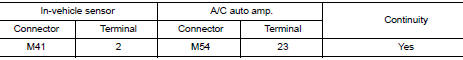
Is the inspection result normal? YES >> GO TO 3.
NO >> Repair harness or connector.
3.CHECK IN-VEHICLE SENSOR
Check in-vehicle sensor. Refer to HAC-62, "Component Inspection".
Is the inspection result normal? YES >> Replace A/C auto amp. Refer to HAC-103, "Removal and Installation".
NO >> Replace in-vehicle sensor. Refer to HAC-105, "Removal and Installation".
4.CHECK IN-VEHCILE SENSOR POWER SUPPLY CIRCUIT FOR OPEN
- Turn ignition switch OFF.
- Disconnect A/C auto amp. connector.
- Check continuity between in-vehicle sensor harness connector and A/C auto amp. harness connector.
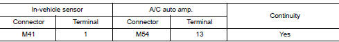
Is the inspection result normal? YES >> GO TO 5.
NO >> Repair harness or connector.
5.CHECK IN-VEHICLE SENSOR POWER SUPPLY CIRCUIT FOR GROUND SHORT
Check continuity between in-vehicle sensor harness connector and ground.
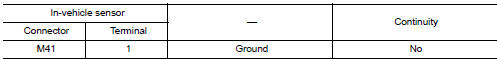
Is the inspection result normal? YES >> GO TO 6.
NO >> Repair harness or connector.
6.CHECK IN-VEHICLE SENSOR POWER SUPPLY CIRCUIT FOR POWER SHORT
- Turn ignition switch ON.
- Check voltage between in-vehicle sensor harness connector and ground.
Is the inspection result normal? YES >> Replace A/C auto amp. Refer to HAC-103, "Removal and Installation".
NO >> Repair harness or connector.
Component Inspection
1.CHECK IN-VEHICLE SENSOR
- Turn ignition switch OFF.
- Disconnect in-vehicle sensor connector.
- Check resistance between in-vehicle sensor terminals.
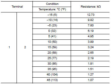
Is the inspection result normal? YES >> Inspection End.
NO >> Replace in-vehicle sensor. Refer to HAC-105, "Removal and Installation".
B24A9 SUNLOAD SENSOR
DTC Logic
DTC DETECTION LOGIC
NOTE:
- If DTC is displayed along with DTC U1000 or U1010, first diagnose the DTC U1000 or U1010. Refer to HAC- 53, "DTC Logic" (U1000) or HAC-54, "DTC Logic" (U1010).
- Sunload sensor may register a malfunction when indoors, at
dusk, or at other times when light is insufficient.
When performing the diagnosis indoors, light the sunload sensor with a lamp (60W or more).
| DTC | Items (CONSULT screen terms) | DTC detection condition | Possible cause |
| B24A9 | SUNLOAD SEN (SHORT) | Detected calorie at sunload sensor 1677 w/m2 (1442 kcal/m2·h) or more |
|
| SUNLOAD SEN (OPEN) | Detected calorie at sunload sensor 33 w/m2 (28 kcal/m2·h) |
DTC CONFIRMATION PROCEDURE
1.CHECK WITH SELF-DIAGNOSIS FUNCTION OF CONSULT
- Using CONSULT, perform “Self Diagnostic Result” of “HVAC”.
- Check if any DTC No. is displayed in the self-diagnosis results.
NOTE:
- If DTC is displayed along with DTC U1000 or U1010, first diagnose the DTC U1000 or U1010. Refer to HAC- 53, "DTC Logic" (U1000) or HAC-54, "DTC Logic" (U1010).
- Sunload sensor may register a malfunction when indoors, at dusk, or at other times when light is insufficient.
When performing the diagnosis indoors, light the sunload sensor with a lamp (60W or more).
Is DTC No.“B24A9” displayed? YES >> Perform trouble diagnosis for the sunload sensor. Refer to HAC-64, "Diagnosis Procedure".
NO >> Inspection End.
Diagnosis Procedure
Regarding Wiring Diagram information, refer to HAC-35, "Wiring Diagram".
NOTE: This DTC can be set if the BCM is placed in transit mode. Confirm if the DTC is CURRENT or PAST. If PAST, perform the following steps before carrying out Diagnosis Procedure.
- Clear DTC using CONSULT. Refer to HAC-22, "CONSULT Function (HVAC)".
- Perform OPERATION INSPECTION. Refer to HAC-48, "Work Procedure".
- Perform “Self Diagnostic Result” of “HVAC” using CONSULT. Refer to HAC-22, "CONSULT Function (HVAC)".
- If DTC resets, proceed with Diagnosis Procedure.
1.CHECK SUNLOAD SENSOR POWER SUPPLY
- Disconnect sunload sensor connector.
- Turn ignition switch ON.
- Check voltage between sunload sensor harness connector and ground.
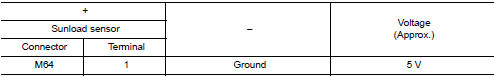
Is the inspection result normal? YES >> GO TO 2.
NO >> GO TO 4.
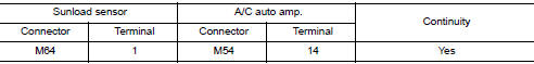
2.CHECK CONTINUITY BETWEEN SUNLOAD SENSOR AND A/C AUTO AMP.
- Turn ignition switch OFF.
- Disconnect A/C auto amp. connector.
- Check continuity between sunload sensor harness connector and A/C auto amp. harness connector.
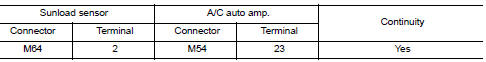
Is the inspection result normal? YES >> GO TO 3.
NO >> Repair harness or connector.
3.CHECK SUNLOAD SENSOR
- Reconnect sunload sensor connector and A/C auto amp. connector.
- Check sunload sensor. Refer to HAC-65, "Component Inspection".
Is the inspection result normal? YES >> Replace A/C auto amp. Refer to HAC-103, "Removal and Installation".
NO >> Replace sunload sensor. Refer to HAC-106, "Removal and Installation".
4.CHECK CONTINUITY BETWEEN SUNLOAD SENSOR AND A/C AUTO AMP.
- Turn ignition switch OFF.
- Disconnect A/C auto amp. connector.
- Check continuity between sunload sensor harness connector and A/C auto amp. harness connector.
- Check continuity between sunload sensor harness connector and ground.
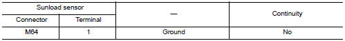
Is the inspection result normal? YES >> Replace A/C auto amp. Refer to HAC-103, "Removal and Installation".
NO >> Repair harness or connector.
Component Inspection
1.CHECK SUNLOAD SENSOR
- Turn ignition switch ON.
- Check voltage between A/C auto amp. harness connector and ground.
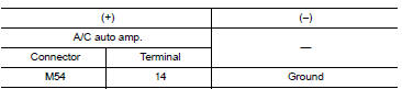
NOTE: Select a place in direct sunlight when checking sunload sensor. Is the inspection result normal? YES >> Inspection End.
NO >> Replace sunload sensor. Refer to HAC-106, "Removal and Installation".
B24BB LEFT AIR MIX DOOR MOTOR
DTC Logic
DTC DETECTION LOGIC
NOTE:
- If DTC is displayed along with DTC U1000, first perform the trouble diagnosis for DTC U1000. Refer to HAC- 53, "DTC Logic".
- If DTC is displayed along with DTC U1010, first perform the trouble diagnosis for DTC U1010. HAC-54, "DTC Logic".
- If air mix door motors DTC (B24BB – B24BD) are detected, there is probably a disconnected connector or an open circuit in air mix door motor drive power supply harness.
| DTC | Items (CONSULT screen terms) | DTC detection condition | Possible cause |
| B24BB | DR AIR MIX DOOR MOT | Short or open circuit of air mix door motor drive signal. |
|
DTC CONFIRMATION PROCEDURE
1.PERFORM DTC CONFIRMATION PROCEDURE
 With CONSULT
- Turn ignition switch ON.
- Select “Self Diagnostic Result” mode of “HVAC” using CONSULT.
- Check DTC.
Is DTC detected? YES >> Refer to HAC-70, "Diagnosis Procedure".
NO >> Inspection End.
Diagnosis Procedure
Regarding Wiring Diagram information, refer to HAC-35, "Wiring Diagram".
1.CHECK AIR MIX DOOR MOTOR LH POWER SUPPLY
- Turn ignition switch OFF.
- Disconnect air mix door motor LH connector.
- Turn ignition switch ON.
- Check voltage between air mix door motor LH harness connector and ground.
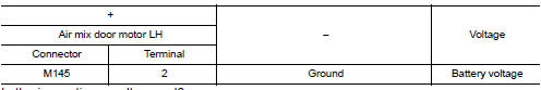
Is the inspection result normal? YES >> GO TO 3.
NO >> GO TO 2.
2.CHECK AIR MIX DOOR MOTOR LH POWER SUPPLY CIRCUIT FOR OPEN
- Disconnect A/C auto amp. connector.
- Check continuity between air mix door motor LH harness connector and A/C auto amp. harness connector.
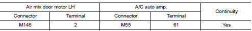
Is the inspection result normal? YES >> Replace A/C auto amp. Refer to HAC-103, "Removal and Installation".
NO >> Repair harness or connector.
3.CHECK AIR MIX DOOR MOTOR LH DRIVE SIGNAL CIRCUIT FOR OPEN
- Turn ignition switch OFF.
- Disconnect A/C auto amp. connector.
- Check continuity between air mix door motor LH harness connector and A/C auto amp. harness connector.
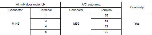
Is the inspection result normal? YES >> GO TO 4.
NO >> Repair harness or connector.
4.CHECK AIR MIX DOOR MOTOR LH DRIVE SIGNAL CIRCUIT FOR SHORT
Check continuity between air mix door motor LH harness connector and A/C auto amp. harness connector.
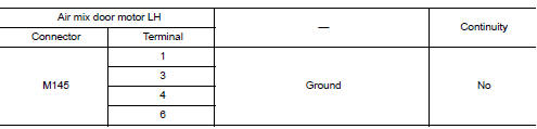
Is the inspection result normal? YES >> GO TO 5.
NO >> Repair harness or connector.
5.CHECK AIR MIX DOOR MOTOR LH
Check air mix door motor LH. Refer to HAC-71, "Component Inspection".
Is the inspection result normal? YES >> Replace A/C auto amp. Refer to HAC-103, "Removal and Installation".
NO >> Replace air mix door motor LH. Refer to HAC-110, "AIR MIX DOOR MOTOR : Removal and Installation".
Component Inspection
1.CHECK AIR MIX DOOR MOTOR LH
- Remove air mix door motor LH. Refer to HAC-110, "AIR MIX DOOR MOTOR : Removal and Installation".
- Check resistance between air mix door motor LH terminals. Refer to applicable table for the normal value.
Is the inspection result normal? YES >> Inspection End.
NO >> Replace air mix door motor LH. Refer to HAC-110, "AIR MIX DOOR MOTOR : Removal and Installation".
B24BD RIGHT AIR MIX DOOR MOTOR
DTC Logic
DTC DETECTION LOGIC
NOTE:
- If DTC is displayed along with DTC U1000, first perform the trouble diagnosis for DTC U1000. Refer to HAC- 53, "DTC Logic".
- If DTC is displayed along with DTC U1010, first perform the trouble diagnosis for DTC U1010. HAC-54, "DTC Logic".
- If air mix door motors DTC (B24BB – B24BD) are detected, there is probably a disconnected connector or an open circuit in air mix door motor drive power supply harness.
| DTC | Items (CONSULT screen terms) | DTC detection condition | Possible cause |
| B24BD | AS AIR MIX DOOR MOT | Short or open circuit of air mix door motor drive signal. |
|
DTC CONFIRMATION PROCEDURE
1.PERFORM DTC CONFIRMATION PROCEDURE
 With CONSULT
- Turn ignition switch ON.
- Select “Self Diagnostic Result” mode of “HVAC” using CONSULT.
- Check DTC.
Is DTC detected? YES >> Refer to HAC-70, "Diagnosis Procedure".
NO >> Inspection End.
Diagnosis Procedure
Regarding Wiring Diagram information, refer to HAC-35, "Wiring Diagram".
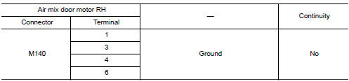
1.CHECK AIR MIX DOOR MOTOR RH POWER SUPPLY
- Turn ignition switch OFF.
- Disconnect air mix door motor RH connector.
- Turn ignition switch ON.
- Check voltage between air mix door motor RH harness connector and ground.
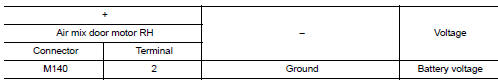
Is the inspection result normal? YES >> GO TO 3.
NO >> GO TO 2.
2.CHECK AIR MIX DOOR MOTOR RH POWER SUPPLY CIRCUIT FOR OPEN
- Disconnect A/C auto amp. connector.
- Check continuity between air mix door motor RH harness connector and A/C auto amp. harness connector.
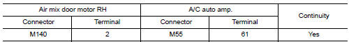
Is the inspection result normal? YES >> Replace A/C auto amp. Refer to HAC-103, "Removal and Installation".
NO >> Repair harness or connector.
3.CHECK AIR MIX DOOR MOTOR DRIVE SIGNAL CIRCUIT FOR OPEN
- Turn ignition switch OFF.
- Disconnect A/C auto amp. connector.
- Check continuity between air mix door motor RH harness connector and A/C auto amp. harness connector.
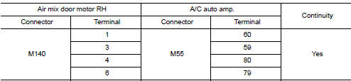
Is the inspection result normal? YES >> GO TO 4.
NO >> Repair harness or connector.
4.CHECK AIR MIX DOOR MOTOR RH DRIVE SIGNAL CIRCUIT FOR SHORT
Check continuity between air mix door motor RH harness connector and A/C auto amp. harness connector.
Is the inspection result normal? YES >> GO TO 5.
NO >> Repair harness or connector.
5.CHECK AIR MIX DOOR MOTOR RH
Check air mix door motor RH. Refer to HAC-71, "Component Inspection".
Is the inspection result normal? YES >> Replace A/C auto amp. Refer to HAC-103, "Removal and Installation".
NO >> Replace air mix door motor RH. Refer to HAC-110, "AIR MIX DOOR MOTOR : Removal and Installation".
Component Inspection
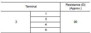
1.CHECK AIR MIX DOOR MOTOR RH
- Remove air mix door motor RH. Refer to HAC-110, "AIR MIX DOOR MOTOR : Removal and Installation".
- Check resistance between air mix door motor RH terminals. Refer to applicable table for the normal value.
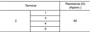
Is the inspection result normal? YES >> Inspection End.
NO >> Replace air mix door motor RH. Refer to HAC-110, "AIR MIX DOOR MOTOR : Removal and Installation".
B24B4 A/C CONTROL
DTC Logic
DTC DETECTION LOGIC
| DTC | Items (CONSULT screen terms) | DTC detection condition | Possible cause |
| B24B4 | A/C CONTROL COMM | When A/C auto amp. is not transmitting or receiving communication signal for 2 or more seconds. |
|
DTC CONFIRMATION PROCEDURE
1.PERFORM DTC CONFIRMATION PROCEDURE
 With CONSULT
- Turn ignition switch ON.
- Using CONSULT, perform “Self Diagnostic Result” of “HVAC”.
- Check if any DTC No. is displayed in the self-diagnosis results.
Is DTC detected? YES >> Refer to HAC-73, "Diagnosis Procedure".
NO >> Inspection End.
Diagnosis Procedure
Regarding Wiring Diagram information, refer to HAC-35, "Wiring Diagram".
1.CHECK WITH SELF-DIAGNOSIS FUNCTION OF CONSULT
- Using CONSULT, perform “Self Diagnostic Result” of “HVAC”.
- Check if any DTC No. is displayed in the self-diagnosis results.
NOTE: If DTC is displayed along with DTC U1000 or U1010, first diagnose the DTC U1000 or U1010. Refer to HAC- 53, "DTC Logic" (U1000) or HAC-54, "DTC Logic" (U1010). Is any DTC No. displayed? YES >> Perform diagnosis for the applicable DTC. Refer to HAC-32, "DTC Index".
NO >> GO TO 2.
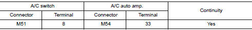
2.CHECK A/C SWITCH COMMUNICATION CIRCUIT CONTINUITY
- Turn ignition switch OFF.
- Disconnect the A/C switch and the A/C auto amp. connectors.
- Check continuity between A/C switch harness connector and A/C auto amp. harness connector.
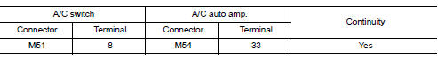
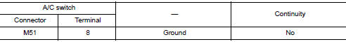
- Check continuity between A/C switch harness connector and ground.
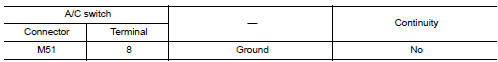
Is the inspection result normal?
YES >> Replace A/C switch. Refer to HAC-102, "Removal and Installation".
NO >> Repair harness or connector.
B24B6 A/C CONTROL
DTC Logic
DTC DETECTION LOGIC
| DTC | Items (CONSULT screen terms) | DTC detection condition | Possible cause |
| B24B6 | A/C CONTROL COMM | When A/C auto amp. is not transmitting or receiving communication signal for 2 or more seconds. |
|
DTC CONFIRMATION PROCEDURE
1.PERFORM DTC CONFIRMATION PROCEDURE
With CONSULT
- Turn ignition switch ON.
- Using CONSULT, perform “Self Diagnostic Result” of “HVAC”.
- Check if any DTC No. is displayed in the self-diagnosis results.
Is DTC detected? YES >> Refer to HAC-75, "Diagnosis Procedure".
NO >> Inspection End.
Diagnosis Procedure
Regarding Wiring Diagram information, refer to HAC-35, "Wiring Diagram".
1.CHECK WITH SELF-DIAGNOSIS FUNCTION OF CONSULT
- Using CONSULT, perform “Self Diagnostic Result” of “HVAC”.
- Check if any DTC No. is displayed in the self-diagnosis results.
NOTE: If DTC is displayed along with DTC U1000 or U1010, first diagnose the DTC U1000 or U1010. Refer to HAC- 53, "DTC Logic" (U1000) or HAC-54, "DTC Logic" (U1010). Is any DTC No. displayed? YES >> Perform diagnosis for the applicable DTC. Refer to HAC-32, "DTC Index".
NO >> GO TO 2.
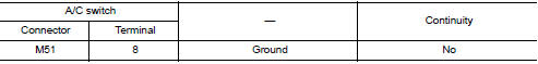
2.CHECK A/C SWITCH COMMUNICATION CIRCUIT CONTINUITY
- Turn ignition switch OFF.
- Disconnect the A/C switch and the A/C auto amp. connectors.
- Check continuity between A/C switch harness connector and A/C auto amp. harness connector.
- Check continuity between A/C switch harness connector and ground.
Is the inspection result normal?
YES >> Replace A/C switch. Refer to HAC-102, "Removal and Installation".
NO >> Repair harness or connector.
B24B7 INTAKE DOOR MOTOR
DTC Logic
DTC DETECTION LOGIC
NOTE:
- If DTC is displayed along with DTC U1000, first perform the trouble diagnosis for DTC U1000. Refer to HAC- 53, "DTC Logic".
- If DTC is displayed along with DTC U1010, first perform the trouble diagnosis for DTC U1010. HAC-54, "DTC Logic".
- If mode door motors DTC (B24B7 – B24B9) are detected, there is probably a disconnected connector or an open circuit in mode door motor drive power supply harness.
| DTC | Items (CONSULT screen terms) | DTC detection condition | Possible cause |
| B24B7 | INTAKE DOOR MOTOR | Short or open circuit of intake door motor drive signal. |
|
DTC CONFIRMATION PROCEDURE
1.PERFORM DTC CONFIRMATION PROCEDURE
 With CONSULT
- Start engine.
- Select “Self Diagnostic Result” mode of “HVAC” using CONSULT.
- Check DTC.
Is DTC detected? YES >> Refer to HAC-77, "Diagnosis Procedure".
NO >> Inspection End.
Diagnosis Procedure
Regarding Wiring Diagram information, refer to HAC-35, "Wiring Diagram".
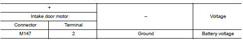
1.CHECK INTAKE DOOR MOTOR POWER SUPPLY
- Turn ignition switch OFF.
- Disconnect intake door motor connector.
- Turn ignition switch ON.
- Check voltage between intake door motor harness connector and ground.
Is the inspection result normal? YES >> GO TO 3.
NO >> GO TO 2.
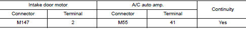
2.CHECK INTAKE DOOR MOTOR DRIVE SIGNAL CIRCUIT FOR OPEN
- Turn ignition switch OFF.
- Disconnect A/C auto amp. connector.
- Check continuity between intake door motor harness connector and A/C auto amp. harness connector.
Is the inspection result normal? YES >> Replace A/C auto amp. Refer to HAC-103, "Removal and Installation".
NO >> Repair harness or connector.
3.CHECK INTAKE DOOR MOTOR DRIVE SIGNAL CIRCUIT FOR OPEN
- Turn ignition switch OFF.
- Disconnect A/C auto amp. connector.
- Check continuity between intake door motor harness connector and A/C auto amp. harness connector.
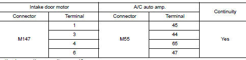
Is the inspection result normal? YES >> GO TO 4.
NO >> Repair harness or connector.
4.CHECK INTAKE DOOR MOTOR DRIVE SIGNAL CIRCUIT FOR SHORT
Check continuity between intake door motor harness connector and A/C auto amp. harness connector.
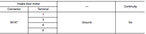
the inspection result normal? YES >> GO TO 5.
NO >> Repair harness or connector.
5.CHECK INTAKE DOOR MOTOR
Check intake door motor. Refer to HAC-81, "Component Inspection".
Is the inspection result normal? YES >> Replace A/C auto amp. Refer to HAC-103, "Removal and Installation".
NO >> Replace intake door motor. Refer to HAC-110, "INTAKE DOOR MOTOR : Removal and Installation".
Component Inspection (Motor)
1.CHECK INTAKE DOOR MOTOR
- Remove intake door motor. Refer to HAC-110, "INTAKE DOOR MOTOR : Removal and Installation".
- Check resistance between intake door motor terminals. Refer to applicable table for the normal value.
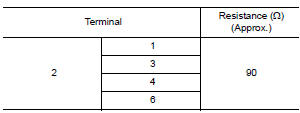
Is the inspection result normal? YES >> Inspection End.
NO >> Replace intake door motor. Refer to HAC-110, "INTAKE DOOR MOTOR : Removal and Installation".
B24B9 MODE DOOR MOTOR
DTC Logic
DTC DETECTION LOGIC
NOTE:
- If DTC is displayed along with DTC U1000, first perform the trouble diagnosis for DTC U1000. Refer to HAC- 53, "DTC Logic".
- If DTC is displayed along with DTC U1010, first perform the trouble diagnosis for DTC U1010. HAC-54, "DTC Logic".
- If mode door motors DTC (B24B7 – B24B9) are detected, there is probably a disconnected connector or an open circuit in mode door motor drive power supply harness.
| DTC | Items (CONSULT screen terms) | DTC detection condition | Possible cause |
| B24B9 | MODE DOOR MOTOR | Short or open circuit of mode door motor drive signal. |
|
DTC CONFIRMATION PROCEDURE
1.PERFORM DTC CONFIRMATION PROCEDURE
 With CONSULT
- Turn ignition switch ON.
- Select “Self Diagnostic Result” mode of “HVAC” using CONSULT.
- Check DTC.
Is DTC detected? YES >> Refer to HAC-80, "Diagnosis Procedure".
NO >> Inspection End.
Diagnosis Procedure
Regarding Wiring Diagram information, refer to HAC-35, "Wiring Diagram".
1.CHECK MODE DOOR MOTOR POWER SUPPLY
- Turn ignition switch OFF.
- Disconnect mode door motor connector.
- Turn ignition switch ON.
- Check voltage between mode door motor harness connector and ground.
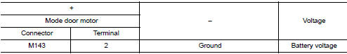
Is the inspection result normal? YES >> GO TO 3.
NO >> GO TO 2.
2.CHECK MODE DOOR MOTOR POWER SUPPLY CIRCUIT FOR OPEN
- Disconnect A/C auto amp. connector.
- Check continuity between mode door motor harness connector and A/C auto amp. harness connector.
Is the inspection result normal? YES >> Replace A/C auto amp. Refer to HAC-103, "Removal and Installation".
NO >> Repair harness or connector.
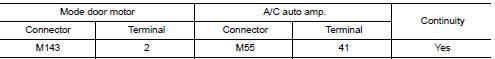
3.CHECK MODE DOOR MOTOR DRIVE SIGNAL CIRCUIT FOR OPEN
- Turn ignition switch OFF.
- Disconnect A/C auto amp. connector.
- Check continuity between mode door motor harness connector and A/C auto amp. harness connector.
Is the inspection result normal? YES >> GO TO 4.
NO >> Repair harness or connector.
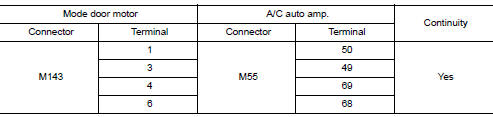
4.CHECK MODE DOOR MOTOR DRIVE SIGNAL CIRCUIT FOR SHORT
Check continuity between mode door motor harness connector and A/C auto amp. harness connector.
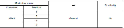
Is the inspection result normal? YES >> GO TO 5.
NO >> Repair harness or connector.
5.CHECK MODE DOOR MOTOR
Check mode door motor. Refer to HAC-81, "Component Inspection".
Is the inspection result normal? YES >> Replace A/C auto amp. Refer to HAC-103, "Removal and Installation".
NO >> Replace mode door motor. Refer to HAC-110, "MODE DOOR MOTOR : Removal and Installation".
Component Inspection
1.CHECK MODE DOOR MOTOR
- Remove mode door motor. Refer to HAC-110, "MODE DOOR MOTOR : Removal and Installation".
- Check resistance between mode door motor terminals. Refer to applicable table for the normal value.
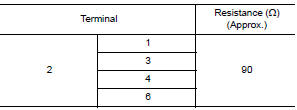
Is the inspection result normal? YES >> Inspection End.
NO >> Replace mode door motor. Refer to HAC-110, "MODE DOOR MOTOR : Removal and Installation".
B24C3 BLOWER MOTOR FEEDBACK
DTC Logic
DTC DETECTION LOGIC
| DTC | Items (CONSULT screen terms) | DTC detection condition | Possible cause |
| B24C3 | BLOWER MOTOR FEEDBACK | Short or open circuit of blower motor feedback circuit. |
|
DTC CONFIRMATION PROCEDURE
1.PERFORM DTC CONFIRMATION PROCEDURE
 With CONSULT
- Turn ignition switch ON.
- Using CONSULT, perform “Self Diagnostic Result” of “HVAC”.
- Check if any DTC No. is displayed in the self-diagnosis results.
Is DTC detected? YES >> Refer to HAC-83, "Diagnosis Procedure".
NO >> Inspection End.
Diagnosis Procedure
Regarding Wiring Diagram information, refer to HAC-35, "Wiring Diagram".
NOTE: This DTC can be set if the BCM is placed in transit mode. Confirm if the DTC is CURRENT or PAST. If PAST, perform the following steps before carrying out Diagnosis Procedure.
- Clear DTC using CONSULT. Refer to HAC-22, "CONSULT Function (HVAC)".
- Perform OPERATION INSPECTION. Refer to HAC-48, "Work Procedure".
- Perform “Self Diagnostic Result” of “HVAC” using CONSULT. Refer to HAC-22, "CONSULT Function (HVAC)".
- If DTC resets, proceed with Diagnosis Procedure.
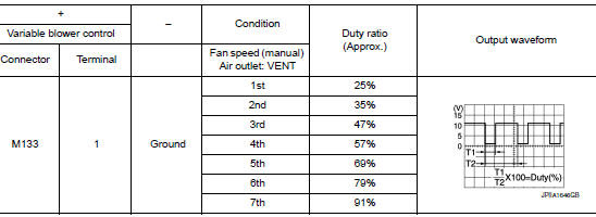
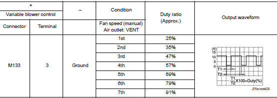
1.CHECK FRONT BLOWER FEEDBACK SIGNAL
- Turn ignition switch ON.
- Set air outlet to VENT.
- Change fan speed from 1st – 7th, and check duty ratios between variable blower control harness connector and ground by using an oscilloscope.
NOTE: Calculate the drive signal duty ratio as shown in the figure. T2 = Approx. 1.6 ms
Is the inspection result normal? YES >> GO TO 2.
NO >> Replace variable blower control. Refer to HAC-112, "Removal and Installation".
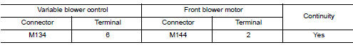
2.CHECK FRONT BLOWER MOTOR FEEDBACK CIRCUIT FOR OPEN
- Turn ignition switch OFF.
- Disconnect variable blower control connector and A/C auto amp.connector.
- Check continuity between variable blower control harness connector and A/C auto amp. connector.
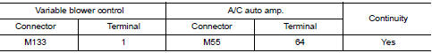
Is the inspection result normal? YES >> Replace A/C auto amp. Refer to VTL-16, "Removal and Installation".
NO >> Repair harness or connector.
B24C6 BLOWER MOTOR CONTROL
DTC Logic
DTC DETECTION LOGI
| DTC | Items (CONSULT screen terms) | DTC detection condition | Possible cause |
| B24C6 | BLOWER MOTOR CONTROL | Short or open circuit of blower motor control circuit. |
|
DTC CONFIRMATION PROCEDURE
1.PERFORM DTC CONFIRMATION PROCEDURE
With CONSULT
- Turn ignition switch ON.
- Using CONSULT, perform “Self Diagnostic Result” of “HVAC”.
- Check if any DTC No. is displayed in the self-diagnosis results.
Is DTC detected? YES >> Refer to HAC-85, "Diagnosis Procedure".
NO >> Inspection End.
Diagnosis Procedure
Regarding Wiring Diagram information, refer to HAC-35, "Wiring Diagram".
NOTE: This DTC can be set if the BCM is placed in transit mode. Confirm if the DTC is CURRENT or PAST. If PAST, perform the following steps before carrying out Diagnosis Procedure.
- Clear DTC using CONSULT. Refer to HAC-22, "CONSULT Function (HVAC)".
- Perform OPERATION INSPECTION. Refer to HAC-48, "Work Procedure".
- Perform “Self Diagnostic Result” of “HVAC” using CONSULT. Refer to HAC-22, "CONSULT Function (HVAC)".
- If DTC resets, proceed with Diagnosis Procedure.
1.CHECK FUSE
- Turn ignition switch OFF.
- Check 20A fuses. [Nos. 17 and 27, located in fuse block (J/B)].
NOTE: Refer to PG-64, "Terminal Arrangement". Is the inspection result normal? YES >> GO TO 2.
NO >> Replace the blown fuse after repairing the affected circuit.
2.CHECK VARIABLE BLOWER CONTROL POWER SUPPLY
- Disconnect variable blower control connector.
- Turn ignition switch ON.
- Check voltage between variable blower control harness connector and ground.
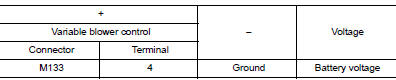
Is the inspection result normal? YES >> GO TO 4.
NO >> GO TO 3.
3.CHECK FRONT BLOWER RELAY
- Turn ignition switch OFF.
- Check front blower relay. Refer to HAC-88, "Component Inspection (Front Blower Relay)".
Is the inspection result normal? YES >> Repair harness or connector between variable blower control and fuse.
NO >> Replace front blower relay.
4.CHECK FRONT BLOWER MOTOR POWER SUPPLY
- Connect variable blower control connector.
- Disconnect front blower motor connector.
- Turn ignition switch ON.
- Check voltage between front blower motor harness connector and ground.
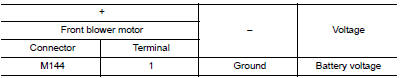
Is the inspection result normal? YES >> GO TO 5.
NO >> Replace variable blower control. Refer to HAC-112, "Removal and Installation".
5.CHECK FRONT BLOWER MOTOR CONTROL CIRCUIT FOR OPEN
- Turn ignition switch OFF.
- Disconnect variable blower control connector.
- Check continuity between variable blower control harness connector and front blower motor harness connector.
Is the inspection result normal? YES >> GO TO 6.
NO >> Repair harness or connector.
6.CHECK FRONT BLOWER MOTOR OPERATION
Check front blower motor operation. Refer to HAC-88, "Component Inspection (Front Blower Motor)".
Is the inspection result normal? YES >> GO TO 7.
NO >> Replace front blower motor. Refer to VTL-16, "Removal and Installation".
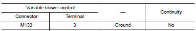
7.CHECK VARIABLE BLOWER CONTROL GROUND CIRCUIT FOR OPEN
- Turn ignition switch OFF.
- Check continuity between variable blower control harness connector and ground.
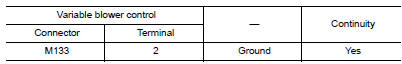
Is the inspection result normal? YES >> GO TO 8.
NO >> Repair harness or connector.
8.CHECK VARIABLE BLOWER CONTROL SIGNAL
- Connect variable blower control connector and A/C auto amp. connector.
- Turn ignition switch ON.
- Set air outlet to VENT.
- Change fan speed from 1st – 7th, and check duty ratios between variable blower control harness connector and ground by using an oscilloscope.
NOTE: Calculate the drive signal duty ratio as shown in the figure. T2 = Approx. 1.6 ms
Is the inspection result normal? YES >> Replace variable blower control. Refer to HAC-112, "Removal and Installation".
NO >> GO TO 9.
9.CHECK VARIABLE BLOWER CONTROL SIGNAL CIRCUIT FOR OPEN
- Turn ignition switch OFF.
- Disconnect variable blower control connector and A/C auto amp. connector.
- Check continuity between variable blower control harness connector and A/C auto amp. harness connector.
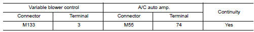
Is the inspection result normal? YES >> GO TO 10.
NO >> Repair harness or connector.
10.CHECK VARIABLE BLOWER CONTROL SIGNAL CIRCUIT FOR SHORT
Check continuity between variable blower control harness connector and ground.
Is the inspection result normal? YES >> Replace A/C auto amp. Refer to HAC-103, "Removal and Installation".
NO >> Repair harness or connector.
Component Inspection (Front Blower Motor)
1.CHECK BLOWER MOTOR
- Connect battery voltage to terminal 1 of blower motor.
- Connect ground to terminal 2 of blower motor.
Does the blower fan operate? YES >> Intermittent incident. Refer to GI-41, "Intermittent Incident".
NO >> Replace blower motor. Refer to VTL-16, "Removal and Installation".
Component Inspection (Front Blower Relay)
1.CHECK FRONT BLOWER RELAY
- Remove front blower relay. Refer to PG-64, "Terminal Arrangement".
- Check continuity between blower relay terminal 3 and 5 when the voltage is supplied between terminal 1 and 2.
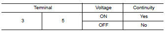
Is the inspection result normal? YES >> Inspection End.
NO >> Replace front blower relay.
B24D4 A/C CONTROL COMMUNICATION
DTC Logic
DTC DETECTION LOGIC
| DTC | Items (CONSULT screen terms) | DTC detection condition | Possible cause |
| B24D4 | A/C CONTROL COMM | When A/C auto amp. is not transmitting or receiving communication signal for 2 or more seconds. |
|
DTC CONFIRMATION PROCEDURE
1.PERFORM DTC CONFIRMATION PROCEDURE
 With CONSULT
- Turn ignition switch ON.
- Using CONSULT, perform “Self Diagnostic Result” of “HVAC”.
- Check if any DTC No. is displayed in the self-diagnosis results.
Is DTC detected? YES >> Refer to HAC-89, "Diagnosis Procedure".
NO >> Inspection End.
Diagnosis Procedure
Regarding Wiring Diagram information, refer to HAC-35, "Wiring Diagram".
1.CHECK WITH SELF-DIAGNOSIS FUNCTION OF CONSULT
- Using CONSULT, perform “Self Diagnostic Result” of “HVAC”.
- Check if any DTC No. is displayed in the self-diagnosis results.
NOTE: If DTC is displayed along with DTC U1000 or U1010, first diagnose the DTC U1000 or U1010. Refer to HAC- 53, "DTC Logic" (U1000) or HAC-54, "DTC Logic" (U1010). Is any DTC No. displayed? YES >> Perform diagnosis for the applicable DTC. Refer to HAC-32, "DTC Index".
NO >> GO TO 2.
2.CHECK A/C SWITCH COMMUNICATION CIRCUIT CONTINUITY
- Turn ignition switch OFF.
- Disconnect the A/C switch and the A/C auto amp. connectors.
- Check continuity between A/C switch harness connector and A/C auto amp. harness connector.
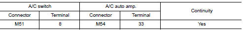
- Check continuity between A/C switch harness connector and ground.
Is the inspection result normal?
YES >> Replace A/C switch. Refer to HAC-102, "Removal and Installation".
NO >> Repair harness or connector.
MAGNET CLUTCH
Component Function Check
 Basic inspection
DIAGNOSIS AND REPAIR WORKFLOW
Work Flow
OVERALL SEQUENCE
DETAILED FLOW
1.INTERVIEW CUSTOMER
Interview the customer to obtain as much information as possible about the
conditions and environ ...
 Symptom diagnosis
HEATER AND AIR CONDITIONING SYSTEM CONTROL SYMPTOMS
Diagnosis Chart By Symptom
NOTE:
Perform the self-diagnoses with CONSULT before performing the symptom diagnosis.
If DTC is detected, perform
...
Other materials:
Radio
With the ignition placed in the ACC or ON position,
press the or POWER
button/VOLUME control knob to turn the radio
on. If you listen to the radio with the engine not
running, the ignition should be placed in the ACC
position.
Radio reception is affected by station signal
strength, distance ...
Sensor maintenance
Sensor maintenance
The distance sensor for the FCW system A is
located behind the front bumper.
To keep the FCW system operating properly, be
sure to observe the following:
Always keep the sensor area of the front
bumper clean.
Do not strike or damage the areas around
...
Front power window switch (passenger side)
Description
Front power window motor RH will be operated if front power window switch RH
is operated.
Component Function Check
1. CHECK FRONT POWER WINDOW SWITCH RH FUNCTION
Check front power window motor RH operation with front power window switch RH.
Is the inspection result normal?
YES ...
