Nissan Rogue Service Manual: Front disc brake
BRAKE PAD
BRAKE PAD : Inspection
Check brake pad wear thickness from an inspection hole (A) on cylinder body. Check using a scale if necessary.
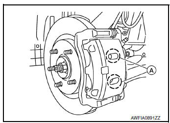
Wear thickness : Refer to BR-55, "Front Disc Brake".
DISC BRAKE ROTOR
DISC BRAKE ROTOR : Inspection
APPEARANCE
Check surface of disc brake rotor for uneven wear, cracks or damage. Replace if any abnormal conditions exist.
RUNOUT
- Check the wheel bearing axial end play before the inspection. Refer to FAX-7, "Inspection"(FWD) or FAX- 38, "Inspection"(AWD).
- Secure the disc brake rotor to the wheel hub and bearing with wheel nuts at two wheel nut locations.
- Inspect the runout with a dial gauge, measured at 10 mm (0.39 in) inside the disc brake rotor edge.
Runout : Refer to BR-55, "Front Disc Brake".
- Find the installation position with a minimum runout by shifting the disc brake rotor-to-wheel hub and bearing installation position by one hole at a time if the runout exceeds the limit value.
- Refinish the disc brake rotor if the runout is outside the limit even after performing the above operation. When refinishing, use Tool.
Tool number : 38-PFM92
CAUTION:
- Check in advance that the thickness of the disc brake rotor is wear thickness + 0.3 mm (0.012 in) or more.
- If the thickness is less than wear thickness + 0.3 mm (0.012 in), replace the disc brake rotor.
Wear thickness : Refer to BR-55, "Front Disc Brake".
THICKNESS
Check the thickness of the disc brake rotor using a micrometer.
Replace the disc brake rotor if the thickness is below the wear limit.
Wear thickness : Refer to BR-55, "Front Disc
Brake".
Thickness variation : Refer to BR-55, "Front Disc
Brake".
 Brake booster
Inspection
Operation
Depress the brake pedal several times at five second intervals with
the engine stopped. Start the engine with the brake pedal fully
depressed. Check that the clearance between ...
 Rear disc brake
BRAKE PAD
BRAKE PAD : Inspection
INSPECTION
Check brake pad wear thickness from an inspection hole (A) on cylinder
body. Check using a scale if necessary.
Wear thickness : Refer to BR-55, &qu ...
Other materials:
The parking brake release warning continues displaying,
or does not display
Description
The parking brake warning is displayed during vehicle travel even though
the parking brake is released.
The parking brake warning is not displayed even though driving the
vehicle with the parking brake applied.
Diagnosis Procedure
1.CHECK PARKING BRAKE WARNING LAMP ...
Periodic maintenance
IN-CABIN MICROFILTER
Removal and Installation
REMOVAL
Release the tab and remove the in-cabin microfilter cover (1)
from under the RH side of the instrument panel.
CAUTION:
Use care when lifting up on the tab to avoid damaging it.
Remove the in-cabin microfilter (2).
CAUT ...
Service data and specifications (SDS)
Wheel Alignment (Unladen*1)
*1: Fuel, engine coolant, and lubricants are full. Spare tire, jack, hand
tools, and mats are in designated positions.
*2: Since an adjustment mechanism is not included, the value of the left and
right wheels must be used as the standard value.
Wheelarch Height ...
