Nissan Rogue Service Manual: Periodic maintenance
HEADLAMP AIMING ADJUSTMENT
Inspection
PREPARATION BEFORE ADJUSTING
Before performing aiming adjustment, check the following:
- Make sure all tires are inflated to correct pressure.
- Place vehicle and screen on level surface.
- Make sure there is no load in vehicle other than the driver (or equivalent weight placed in driver's position).
- Coolant and engine oil filled to correct level, and fuel tank full.
- Remove cargo and/or luggage to maintain an unloaded vehicle condition.
- Confirm spare tire, jack and tools are properly stowed.
- Carefully wipe off any dirt from headlamp lens.
CAUTION: Do not use organic solvent (thinner, gasoline etc.)
- Place a driver or equivalent weight of 68.5 kg (150 lb) on the driver seat.
- By hand, bounce the front and rear of the vehicle to settle the suspension and eliminate any static load.
- Place the front tires in the straight ahead position.
- Aim each headlamp individually and ensure other headlamp beam pattern is blocked from screen.
NOTE:
- For headlamp aiming details, refer to regulations in your area.
- By regulation, no means for horizontal aim adjustment is provided from the factory; only vertical aim is adjustable.
- Use adjusting screw to perform aiming adjustment.
- Perform headlamp aiming if:
- The vehicle front body has been repaired;
- The front combination lamp has been removed or replaced;
- Any outfitting has been installed;
- The vehicleŌĆÖs standard load condition has been substantially increased.
AIMING ADJUSTMENT SCREW
- Front combination lamp (view from rear)
- Headlamp HI/LO (UP/DOWN) adjustment screw
Aiming Adjustment Procedure
Aiming Chart
- Adjustment screen
- Highest cutoff line height
- Lowest cutoff line height
- Headlamp bulb center (H-V point)
- Distance of headlamp aiming screen from vehicle 7.62 m (25 ft)
- Maximum aim evaluation distance from vertical center on aiming screen 399 mm (3┬░R)
- Minimum aim evaluation distance from vertical center on aiming screen 133 mm (1┬░R)
- Aim evaluation area H. Horizontal aiming evaluation line
- Vertical aiming evaluation line
 Right
Right
A (Highest cutoff line height) -13.3 mm (0.5 in) 0.1┬░ up
B (Lowest cutoff line height) 53.2 mm (2.1 in) 0.4┬░ down
LOW BEAM AND HIGH BEAM
NOTE:
- Basic illuminating area for evaluation and/or adjustment should be within range shown on aiming chart.
- Use adjustment screw to perform aiming adjustment.
- Ensure fog lamps are turned off.
- Block the opposite headlamp from projecting a beam pattern onto the
adjustment screen, using a suitable
object. Aim each headlamp individually.
CAUTION: Do not cover the lens surface with a tape etc. The lens is made of resin.
- Place the screen on the same level and flat surface as the vehicle.
NOTE: Surface should be free of any debris that would cause a difference between the headlamp center and the adjustment screen.
- Face the front of the vehicle to the screen and measure distance between the headlamp center and the screen surface.
Distance between the headlamp center and the screen (D) : 7.62 m (25 ft)
- Start the engine. Turn the headlamp on.
- Determine the preferred vertical aim range dimensions, using the aiming chart.
- Measure the projected beam within the aim evaluation segment on the screen.
- Adjust the beam pattern of each headlamp until the aim evaluation segment (the area relative to both the highest and lowest cutoff line height) is positioned within the vertical aim range dimensions shown on the aiming chart.
FRONT FOG LAMP AIMING ADJUSTMENT
Aiming Adjustment Procedure
Aiming Chart
- Vertical center line of fog lamp (LH)
- Lamp center above ground
- Fog lamp high intensity area (LH)
- Vertical center line of fog lamp (RH)
- Vertical center axis
- 100mm (4in)
NOTE:
- (LH) Fog lamp aiming specifications shown, (RH) similar.
- Check the following conditions before performing the aiming adjustment.
- Keep all tires inflated to correct pressure.
- Place vehicle on level ground.
- See that vehicle is unloaded (except for full levels of coolant, engine oil and fuel, and spare tire, jack, and tools). Have the driver or equivalent weight placed in driver seat.
- When performing adjustment, if necessary, cover the headlamps and opposite fog lamp.
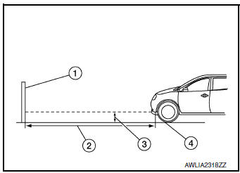
- Set the distance between the screen and the center of the fog
lamp lens as shown.
(1) Aiming screen or a matte white surface
(2) 7.62 m (25 ft)
(3) Floor to center of fog lamp lens
(4) Floor
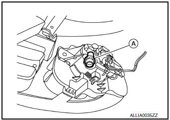
- Turn front fog lamps ON.
- Access adjusting screw (A) from underneath front bumper fascia.
Adjust front fog lamps using adjusting screw so that the top edge of the high intensity zone is at the fog lamp centers above ground.
 Symptom diagnosis
EXTERIOR LIGHTING SYSTEM SYMPTOMS
Symptom Table
CAUTION:
Perform the self-diagnosis with CONSULT before the symptom diagnosis. Perform
the trouble diagnosis
if any DTC is detected.
NORM ...
 Removal and installation
FRONT COMBINATION LAMP
Exploded View
Front fender
Front combination lamp
Clip
Removal and Installation
REMOVAL
Remove front bumper fascia. Refer to EXT-17, "Removal an ...
Other materials:
Heating and cooling unit assembly
Exploded View
Steering Member
Heating and cooling unit assembly
Steering member
Bolt
Nut
Automatic Air Conditioning
Wiring harness
Air mix door duct (LH)
Air mix door duct (RH)
Intake housing gasket
Blower motor
Front foot duct (RH)
...
P2765 input speed sensor B
DTC Description
DTC DETECTION LOGIC
DTC
CONSULT screen terms
(Trouble diagnosis content)
DTC detection condition
P2765
INPUT SPEED SENSOR B
(Input/Turbine Speed Sensor B Circuit)
When 1 is satisfied and any of 2, 3 or 4 is satisfied and this state
is maintaine ...
Water hose
Exploded View
Water outlet
Hose clamp
Water hose A
Clip
CVT oil warmer
Transaxle assembly
Water hose B
Heater thermostat
Water hose C
: Always replace after every
disassembly.
: N┬Ęm (kg-m, ft-lb)
Removal and Installation
REMOVAL
WARNING:
Do not remove the rad ...
