Nissan Rogue (T33) 2021-Present Service Manual: Awd :: Removal and Installation
Rear Wheel Hub and Housing
Exploded View
JAPAN PRODUCTION MODELS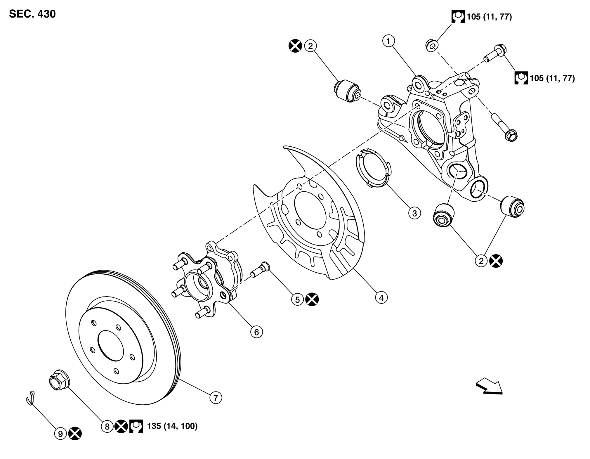
 |
Axle housing |  |
Bushing |  |
Hub cap |
 |
Back plate |  |
Hub bolt |  |
Wheel hub and bearing assembly |
 |
Disc rotor |  |
Wheel hub lock nut |  |
Cotter pin |
| : Nissan Ariya Vehicle front | |||||
 |
: N·m (kg-m, ft-lb) | ||||
 |
: Always replace after every disassembly. | ||||
NORTH AMERICAN PRODUCTION MODELS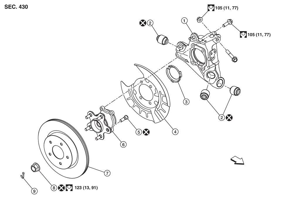
|
Axle housing | |
Bushing | |
Hub cap |
|
Back plate | |
Hub bolt | |
Wheel hub and bearing assembly |
|
Disc rotor | |
Wheel hub lock nut | |
Cotter pin |
| : Nissan Ariya Vehicle front | |||||
|
: N·m (kg-m, ft-lb) | ||||
|
: Always replace after every disassembly. | ||||
Removal and Installation
REMOVAL
Remove wheel and tire. Refer to Exploded View.
Remove wheel sensor from axle housing. Refer to Exploded View.
Remove caliper assembly. Hang caliper assembly in a place where it will not interfere with work. Refer to Removal and Installation.
CAUTION:
Never depress brake pedal while brake caliper is removed.
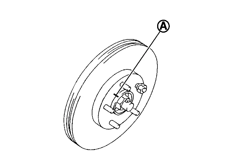
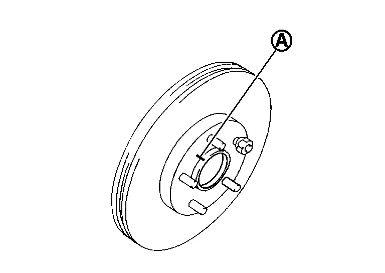
Remove disc rotor.
CAUTION:
-
Put matching marks (A) on the wheel hub and bearing assembly and the disc rotor before removing the disc rotor.
-
Never drop disc rotor.
Remove wheel hub lock nut. Refer to Removal and Installation.
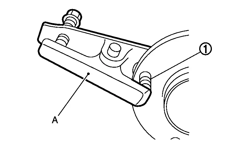
Remove wheel hub and bearing assembly mounting bolts (A) .
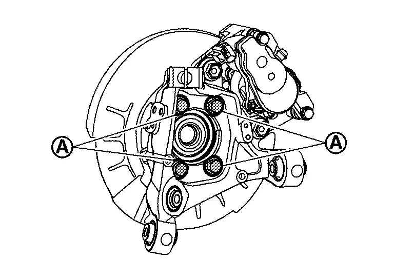
Remove wheel hub and bearing assembly and back plate.
Remove radius rod. Refer to Removal and Installation.
Remove front lower link. Refer to Removal and Installation.
Remove coil spring. Refer to Removal and Installation.
Remove the nut, bolt and brake tube brackets from the rear axle housing. Refer to Exploded View.
Remove rear suspension arm mounting bolts (A) and nuts (B) from axle housing (1).
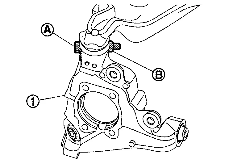
Separate rear suspension arm, and then remove axle housing.
Remove hub bolts (1) from wheel hub and bearing assembly, using the ball joint remover (A) (commercial service tool).
CAUTION:
-
Remove hub bolt only when necessary.
-
Never hammer the hub bolt to avoid impact to the wheel hub and bearing assembly.
-
Pull out the hub bolt in a direction perpendicular to the wheel hub and bearing assembly.
Perform inspection after removal. Refer to Inspection.
INSTALLATION
Note the following, and install in the reverse order of removal.
-
Place a washer (A) as shown in the figure to install the hub bolts (1) by using the tightening force of the nut (B).
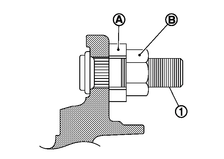
CAUTION:
-
Check that there is no clearance between wheel hub and bearing assembly, and hub bolt.
-
Never reuse hub bolt.
-
-
Align the matching marks (A) made during removal when reusing the disc rotor.
-
Perform inspection after installation. Refer to Inspection.
Inspection
INSPECTION AFTER REMOVAL
Check wheel hub and bearing assembly for wear, cracks, and damage. Replace if there are.
INSPECTION AFTER INSTALLATION
Check wheel sensor harness for proper connection. Refer to Exploded View.
If pressing the piston of rear brake caliper assembly, perform "REMOVAL/REPLACEMENT OF REAR BRAKE PAD OR REAR BRAKE CALIPER". Refer to Description.
Check wheel alignment. Refer to Inspection.
Adjust neutral position of steering angle sensor. Refer to Description.
Rear Drive Shaft
Exploded View
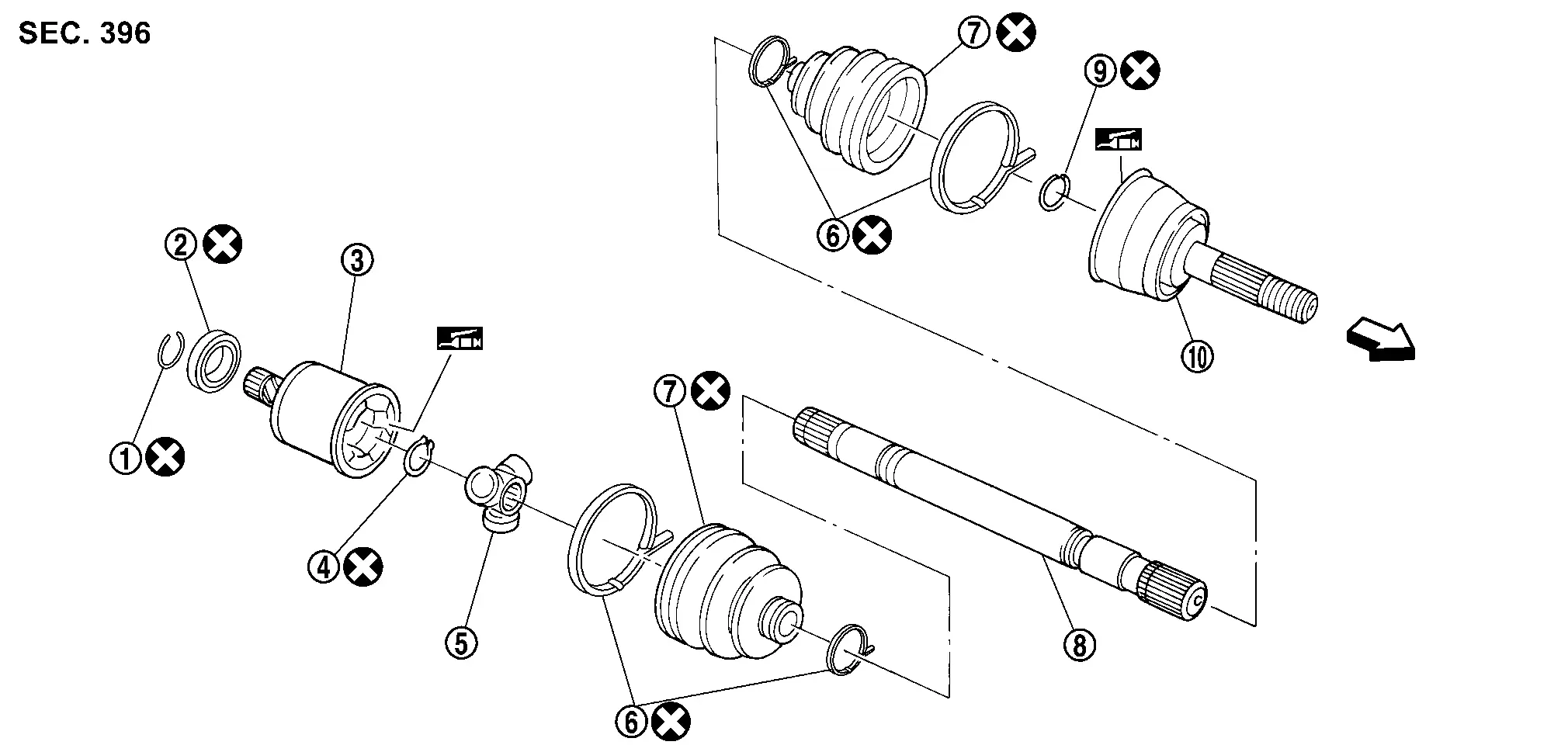
|
Circular clip | |
Dust shield | |
Housing |
|
Snap ring | |
Spider assembly | |
Boot band |
|
Boot | |
Shaft | |
Circular clip |
 |
Joint sub-assembly | ||||
| : Wheel side | |||||
 |
: Fill NISSAN genuine grease or an equivalent. | ||||
|
: Always replace after every disassembly. | ||||
Removal and Installation
REMOVAL
Remove wheel and tire. Refer to Removal & Installation.
Remove wheel sensor from wheel hub and bearing assembly. Refer to Exploded View.
Remove caliper assembly. Hang caliper assembly in a place where it will not interfere with work. Refer to Removal and Installation.
CAUTION:
Never depress brake pedal while brake caliper is removed.
Remove disc rotor. If disc rotor cannot be removed, remove as follows.
CAUTION:
-
Parking brake completely in the released position.
-
Put matching marks (A) on the wheel hub and bearing assembly and the disc rotor before removing the disc rotor.
-
Never drop disc rotor.
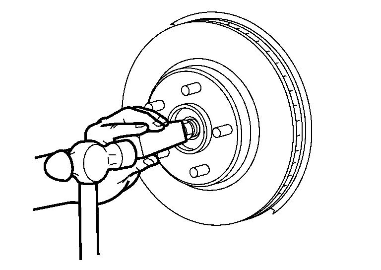
Remove cotter pin, and then loosen wheel hub lock nut, using a wheel hub lock nut wrench (A) (SST: KV40104000).

Patch hub lock nut with a piece of wood. Hammer the wood to disengage wheel hub and bearing assembly from drive shaft.
 NOTE:
NOTE:
Use suitable puller, if wheel hub and bearing assembly and drive shaft cannot be separated even after performing the above procedure.
Remove wheel hub and bearing assembly.
CAUTION:
Remove parking brake assembly only when necessary.
Remove back plate.
Remove hub cap.
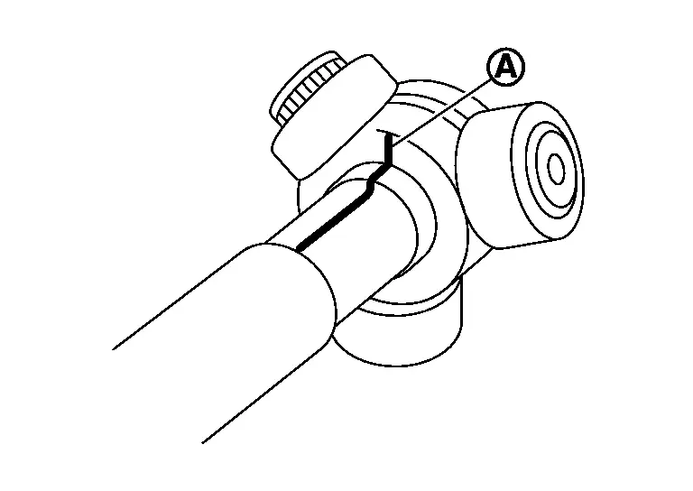
Insert suitable tool (A) between the drive shaft and the transaxle. Remove the drive shaft from the transaxle (LH/RH).
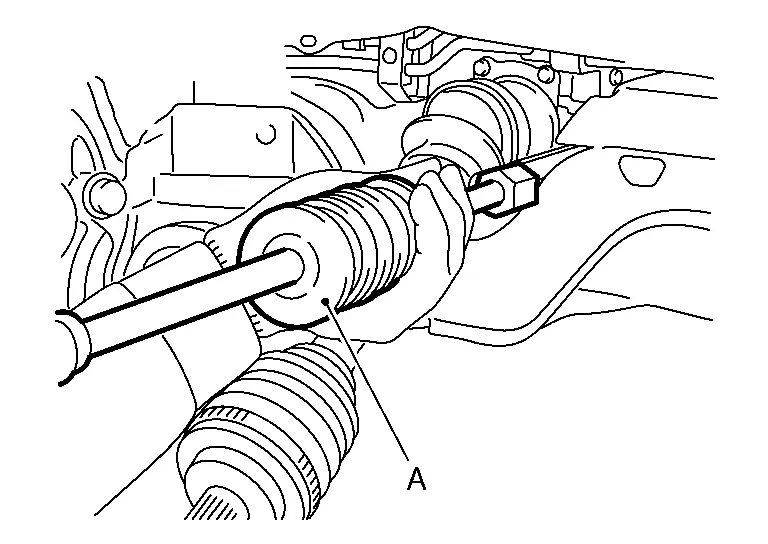
CAUTION:
-
Confirm that the circular clip is attached to the drive shaft.
-
Do not place the drive shaft joint at an extreme angle when removing the drive shaft. Also be careful not to overextend the slide joint.
| Tool (A) | : Drive shaft joint puller (Commercially available) |
Perform inspection after removal. Refer to Inspection.
INSTALLATION
Note the following, and install in the reverse order of removal.
CAUTION:
Always replace side oil seal with new one when installing drive shaft. Refer to Exploded View.
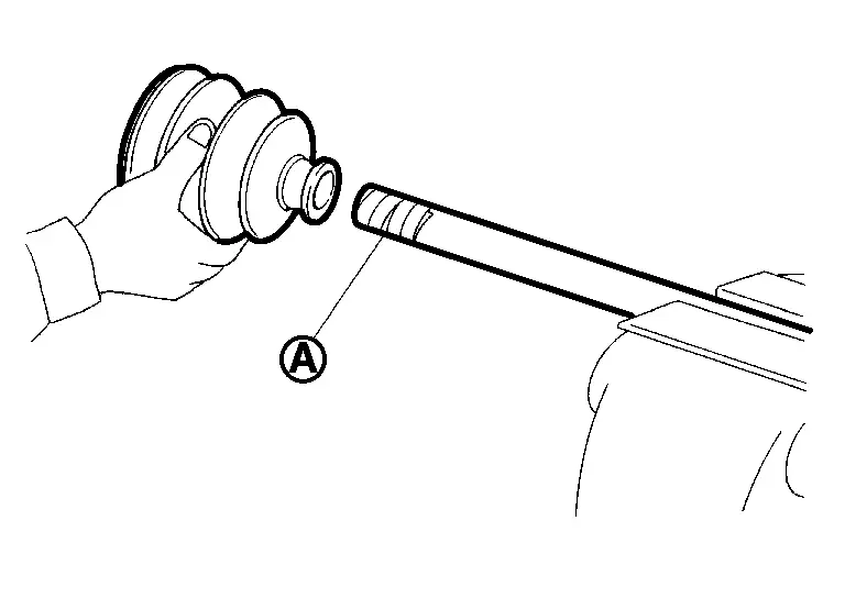
-
Place the protector (A) (SST: KV38107900) onto final drive assembly to prevent damage to the side oil seal while inserting drive shaft. Slide drive shaft sliding joint and tap with a hammer to install securely.
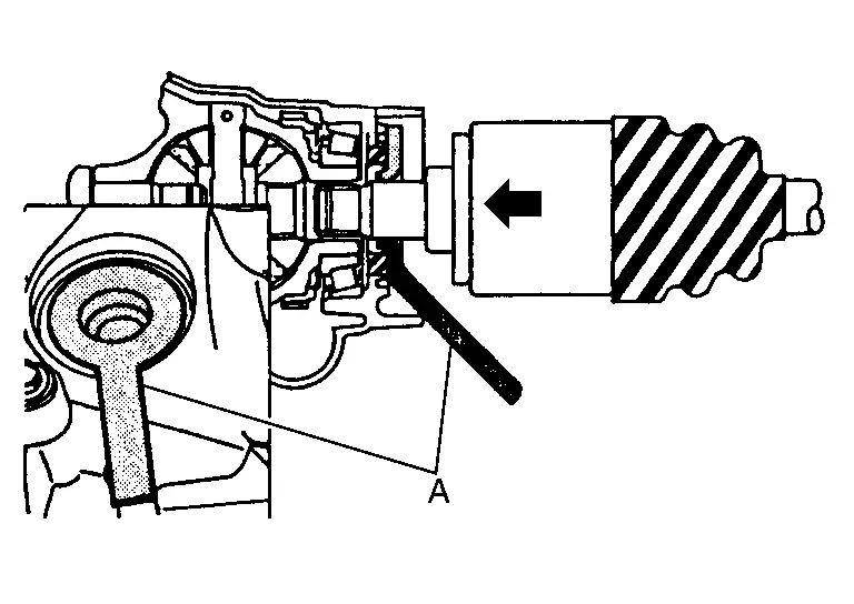
CAUTION:
-
Check that circular clip is completely engaged.
-
Never reuse side oil seal.
-
-
Align the matching marks (A) made during removal when reusing the disc rotor.
-
Perform final tightening of bolts and nuts at suspension arm (rubber bushing), under unladen conditions with tires on level ground.
-
Tighten the wheel hub lock nut to the specified torque. Refer to Exploded View.
-
Perform inspection after installation. Refer to Inspection.
Disassembly and Assembly
DISASSEMBLY
Final Drive Side
Fix shaft with a vise.
CAUTION:
Protect shaft using aluminum or copper plates when fixing with a vise.
Remove boot bands, and then remove boot from housing.
Put matching marks on housing and shaft.
CAUTION:
Use paint or an equivalent for matching marks. Never scratch the surface.
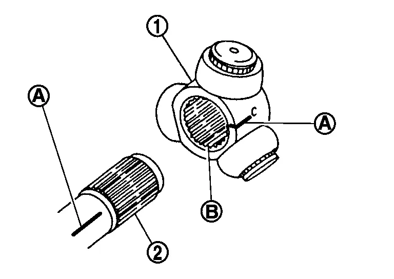
Put matching marks  on the spider assembly and shaft.
CAUTION:
Use paint or an equivalent for matching marks. Never scratch the surface.
Remove snap ring , and then remove spider assembly from shaft.

Remove boot from shaft.
Remove circular clip housing.
Remove dust shield to housing.
Remove old grease on housing with paper towels.
Perform inspection after disassembly. Refer to Inspection.
Wheel Side
Fix shaft with a vise.
CAUTION:
Protect shaft using aluminum or copper plates when fixing with a vise.
Remove boot bands. Then remove boot from joint sub-assembly.
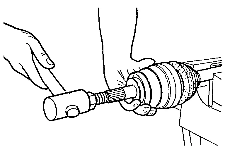
Screw drive shaft puller (A) (commercial service tool) into joint sub-assembly screw part to a length 30 mm (1.18 in) or more. Support drive shaft with one hand and pull out joint sub-assembly from shaft.
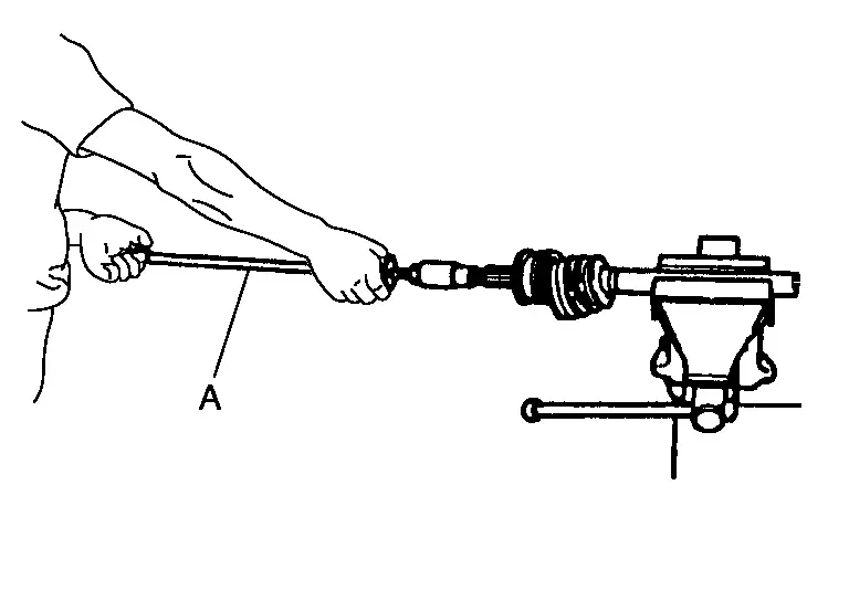
CAUTION:
-
If joint sub-assembly cannot be removed after five or more unsuccessful attempts, replace shaft and joint sub assembly as a set.
-
Align sliding hammer and drive shaft and remove them by pulling directory.
Remove circular clip from shaft.
CAUTION:
Never reuse circular clip.
Remove boot from shaft.
Remove old grease on joint sub-assembly with paper towels.
Perform inspection after disassembly. Refer to Inspection.
ASSEMBLY
Final drive Side
Wrap serration on shaft with tape to protect boot from damage. Install new boot and boot band to shaft.
CAUTION:
Never reuse boot and boot band.
Remove the tape wrapped around the serrated on shaft.
To install the spider assembly , align it with the matching marks on the shaft during the removal, and direct the serration mounting surface  to the shaft.
Secure spider assembly onto shaft with snap ring .
CAUTION:
Never reuse snap ring.
Assemble the housing onto spider assembly, and apply the balance of the specified amount grease.
| Standard | |
| Grease amount | : Refer to Drive Shaft. |
Align matching marks painted when housing were removed.
Install boot securely into grooves (indicated by â*â marks) shown in the figure.
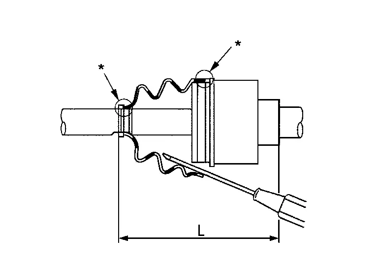
CAUTION:
If there is grease on boot mounting surfaces (indicated by â*â marks) of shaft or housing, boot may be removed. Remove all grease from the surfaces.
To prevent from deformation of the boot, adjust the boot installation length to the value shown below (L) by inserting the suitable tool into the inside of boot from the large diameter side of boot and discharging inside air.
| Standard | |
| L | : Refer to Drive Shaft. |
CAUTION:
-
If the boot installation length exceeds the standard, it may cause breakage in boot.
-
Be careful not to touch the inside of the boot with the tip of tool.
Install new boot bands securely.
CAUTION:
Never reuse boot band.
For low profile type band-
Put boot band in the groove on drive shaft boot. Then fit pawls (
 ) into holes to temporary installation.
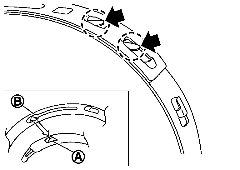 NOTE:
NOTE:
For the large diameter side, fit projection
and guide slit at first. -
Pinch projection on the band with suitable pliers to tighten band.
-
Insert tip of band below end of the pawl.
-
Secure the boot bands using the boot band crimping tool (A) (SST: KV40107300).
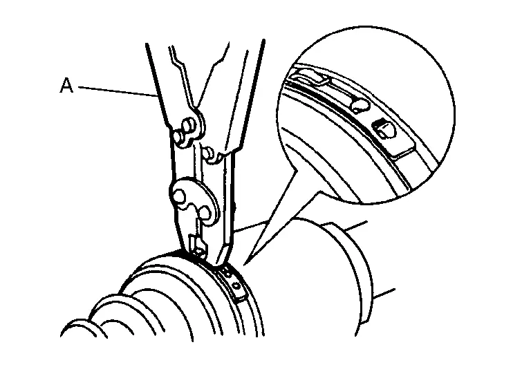
CAUTION:
Never reuse boot band.
NOTE:
Secure boot band so that dimension (M) meets the specification as shown in the figure.
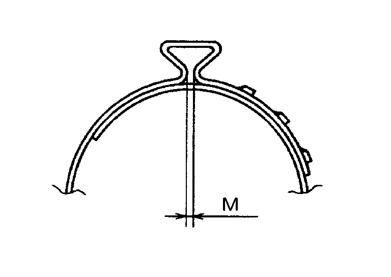
M : 2.3 mm (0.091 in) max
Secure housing and shaft, and then make sure that they are in the correct position when rotating boot. Install them with new boot band when the mounting positions become incorrect.
Install dust shield to housing.
CAUTION:
Never reuse dust shield.
Install circular clip to housing.
CAUTION:
Never reuse circular clip.
Perform inspection after assembly. Refer to Inspection.
Wheel Side
Fill serration slot joint sub-assembly with NISSAN genuine grease or equivalent until the serration slot and ball groove become full to the brim.
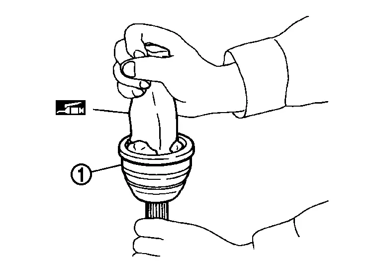
CAUTION:
After applying grease, use a shop cloth to wipe off old grease that has oozed out.
Wrap serrated part of shaft with tape . Install boot band and boot to shaft. Be careful not to damage boot.
CAUTION:
Never reuse boot and boot band.
Remove the tape wrapped around the serrated on shaft.
Position circular clip on groove at the shaft edge.
CAUTION:
Never reuse circular clip.
NOTE:
Drive joint inserter is recommended when installing circular clip.
Align both center axles of the shaft edge and joint sub-assembly. Then assemble shaft with circular clip joint sub-assembly.
Install joint sub-assembly to shaft using plastic hammer.
CAUTION:
Confirm that joint sub-assembly is correctly engaged while rotating drive shaft.
Apply the balance of the specified amount of grease into the boot inside from large diameter side of boot.
| Standard | |
| Grease amount | : Refer to Drive Shaft. |
Install the boot securely into grooves (indicated by â*â marks) shown in the figure.
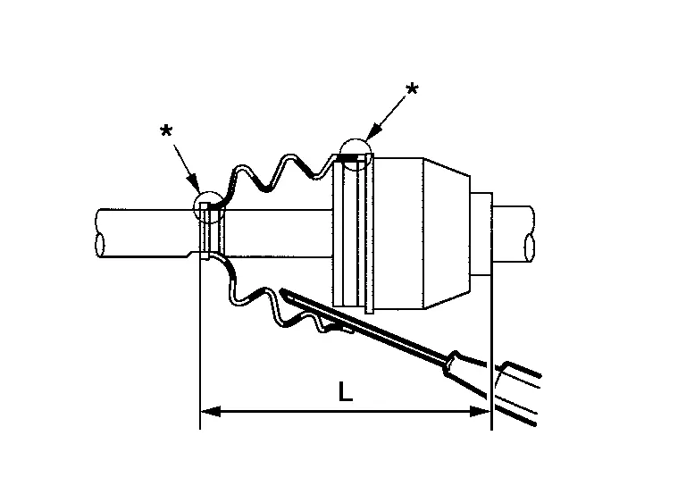
CAUTION:
If grease adheres to the boot mounting surface (with â*â mark) on the shaft or joint sub-assembly, boot may be removed. Remove all grease from the surfaces.
To prevent from deformation of the boot, adjust the boot installation length to the specified value shown below (L) by inserting the suitable tool into inside of the boot from the large diameter side of boot and discharging the inside air.
| Standard | |
| L | : Refer to Drive Shaft. |
CAUTION:
-
If the boot installation length exceeds the standard, it may cause breakage in boot.
-
Be careful not to touch the inside of the boot with the tip of tool.
Secure large and small ends of boot with new boot bands as shown in the figure.
CAUTION:
Never reuse boot band.
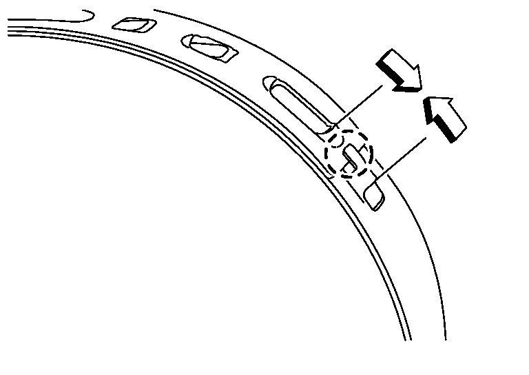
For low profile type band-
Set boot band to the drive shaft boot groove and temporarily fix pawl
of boot band to of boot band.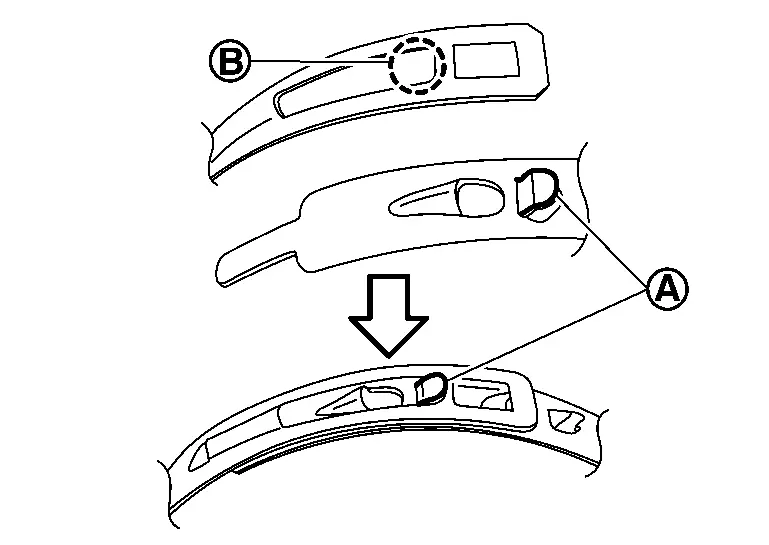
-
Tighten boot band protrusions
with boot band crimping tool (SST: KV40107310) (A) in the direction shown by arrows ().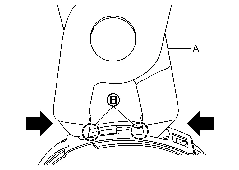
CAUTION:
Securely install boot band
to boot band pawl .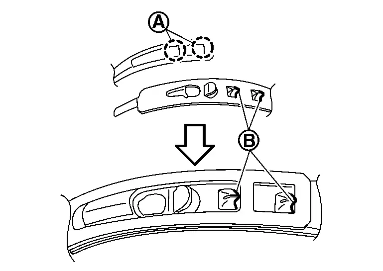
-
Secure the boot bands using the boot band crimping tool (A) (SST: KV40107300).
CAUTION:
Never reuse boot band.
NOTE:
Secure boot band so that dimension (M) meets the specification as shown in the figure.
M : 2.3 mm (0.091 in) max
Secure housing and shaft, and then make sure that they are in the correct position when rotating boot. Install them with new boot band when the mounting positions become incorrect.
Inspection
INSPECTION AFTER REMOVAL
-
Move joint up/down, left/right, and in the axial direction. Check for motion that is not smooth and for significant looseness.
-
Check boot for cracks or other damage, and also for grease leakage.
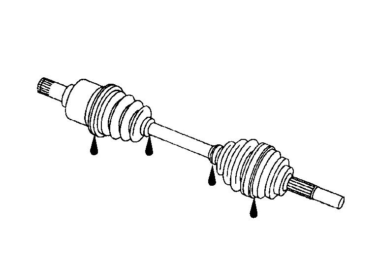
-
If a malfunction is found, disassemble drive shaft, and then replace with new one.
INSPECTION AFTER DISASSEMBLY
Shaft
Check shaft for runout, cracks, or other damage. Replace if there are any abnormal condition.
Joint Sub-Assembly (Wheel Side)
Check the following:
-
Joint sub-assembly for rough rotation and excessive axial looseness.
-
The inside of the joint sub-assembly for entry of foreign material.
-
Joint sub-assembly for compression scars, cracks, and fractures inside of joint sub-assembly.
Replace joint sub-assembly if there are any non-standard conditions of components.
Housing and Spider assembly (Final Drive Side)
Replace housing and spider assembly if there is scratching or wear of housing roller contact surface or spider roller contact surface.
NOTE:
Housing and spider assembly are used in a set.
INSPECTION AFTER INSTALLATION
Check wheel sensor harness for proper connection. Refer to Exploded View.
If pressing the piston of rear brake caliper assembly, perform "REMOVAL/REPLACEMENT OF REAR BRAKE PAD OR REAR BRAKE CALIPER". Refer to Description.
Check wheel alignment. Refer to Inspection.
Adjust neutral position of steering angle sensor. Refer to Work Procedure.
Other materials:
Power Supply and Ground Circuit
Diagnosis Procedure
CHECK ABS ACTUATOR AND ELECTRIC UNIT (CONTROL UNIT) IGNITION POWER SUPPLY
Disconnect 12V battery negative terminal.
Disconnect ABS actuator and electric unit (control unit) harness connector.
Connect 12V battery negative terminal.
Check the voltage between AB ...
Comment utiliser l'ÃĐcran d'informations du vÃĐhicule
L'ÃĐcran d'informations du vÃĐhicule peut Être personnalisÃĐ Ã l'aide de la commande et des boutons situÃĐs sur le volant. Ces commandes du Nissan Rogue permettent de naviguer rapidement, sans quitter la route des yeux.
Commande de dÃĐfilement - permet de naviguer parmi les paramÃĻtres e ...
Informations de base
SÃĐlecteur mode de conduite : ModÃĻles 4x2
SÃĐlecteur mode de conduite : ModÃĻles avec transmission
intÃĐgrale
Ãcran d'informations du vÃĐhicule : ModÃĻles 4x2
Ãcran d'informations du vÃĐhicule : ModÃĻles avec
transmission intÃĐgrale
Le Nissan Rogue propose plusieurs ...