Nissan Rogue (T33) 2021-Present Service Manual: Adas Control Unit :: Removal and Installation. Adas Control Unit 2
Adas Control Unit 2
Removal and Installation
With ProPILOT Assist 1.1
REMOVAL
CAUTION:
Be sure to perform ŌĆ£ADDITIONAL SERVICE WHEN REPLACING ADAS CONTROL UNIT 2ŌĆØ when replacing ADAS control unit 2. Refer to Work Procedure.
Remove center console assembly. Refer to Removal and Installation.
Remove around view monitor control unit. Refer to Removal and Installation.
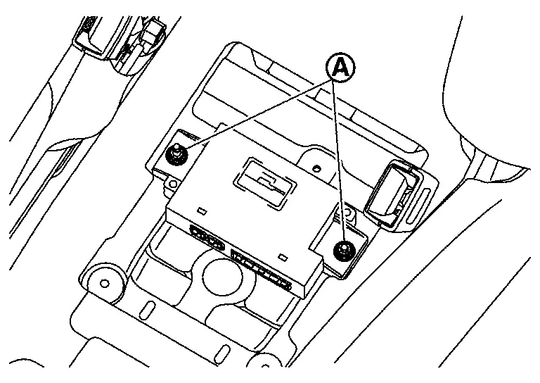
Remove ADAS control unit 2 nuts (A) .
 NOTE:
NOTE:
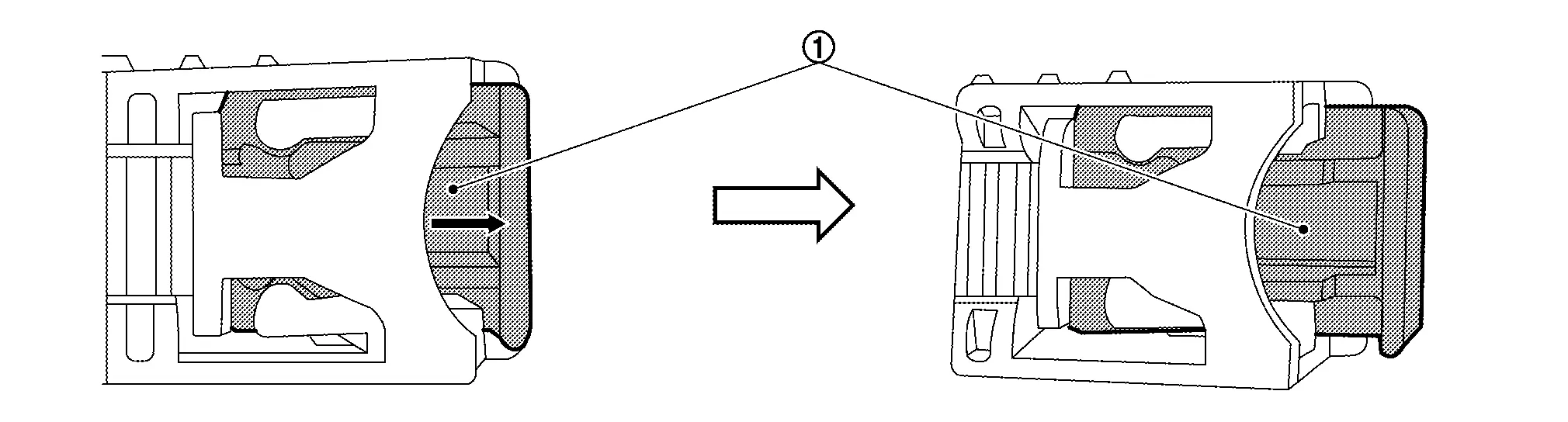
The harness connector is difficult to remove unless removing the ADAS control unit 2 first (The connector lock is located on the lower side).
Release the lock (1) as shown by the arrow in the figure and disconnect the harness connector from the ADAS control unit 2.
INSTALLATION
Note the following, and install in the reverse order of removal.
-
Tighten the ADAS control unit 2 nuts to the specified torque.
| Nuts (A) | : 8 N┬Ęm (0.82 kg-m, 71 in-lb) |
CAUTION:
Be sure to perform ŌĆ£ADDITIONAL SERVICE WHEN REPLACING ADAS CONTROL UNIT 2ŌĆØ when replacing ADAS control unit 2. Refer to Work Procedure.
With ProPILOT Assist 2.1
REMOVAL
CAUTION:
Be sure to perform ŌĆ£ADDITIONAL SERVICE WHEN REPLACING ADAS CONTROL UNIT 2ŌĆØ when replacing ADAS control unit 2. Refer to Work Procedure.
Remove the fusible link box (12V sub battery) (lithium ion battery) and fusible link box bracket. Refer to Removal and Installation.
Release the lock (1) as shown and disconnect the harness connectors from the ADAS control unit 2.
Remove nuts and remove the ADAS control unit 2.
INSTALLATION
Installation is in the reverse order of removal.
-
Tighten the ADAS control unit 2 nuts to the specified torque.
Nuts : 8 N┬Ęm (0.82 kg-m, 71 in-lb)
CAUTION:
Be sure to perform ŌĆ£ADDITIONAL SERVICE WHEN REPLACING ADAS CONTROL UNIT 2ŌĆØ when replacing ADAS control unit 2. Refer to Work Procedure.
Other materials:
P055f Engine Oil Pressure
DTC Description
DTC DETECTION LOGIC DTC
CONSULT screen terms
(Trouble diagnosis content)
DTC detection condition
P055F
Engine oil pressure
(Engine oil pressure out of range)
Diagnosis condition
After ECM self shut-off.
Engine oil temperature is more than -10 Ōäā(14 ...
Component Parts
Chassis Control System
Without Propilot Assist 2.1
Component Parts Location
A.
View with instrument panel assembly removed
No. Component parts Function
1.
BCM (Body Control Module)
BCM transmits the drive mode select switch to the chassis control module via CAN co ...
Dtc/circuit Diagnosis. B2426-12 Spindle Sensor Lh
DTC Description
DTC DETECTION LOGIC DTC No.
CONSULT screen items
(Trouble diagnosis content) DTC Detection Condition
B2426-12
Spindle sensor LH
(Spindle sensor left hand)
Diagnosis condition
When the door unlock operates while ignition switch is OFF (auto ACC OFF status) or the ba ...