Nissan Rogue (T33) 2021-Present Service Manual: 2wd :: Removal and Installation. Rear Wheel Hub and Housing
Rear Wheel Hub and Housing
Exploded View
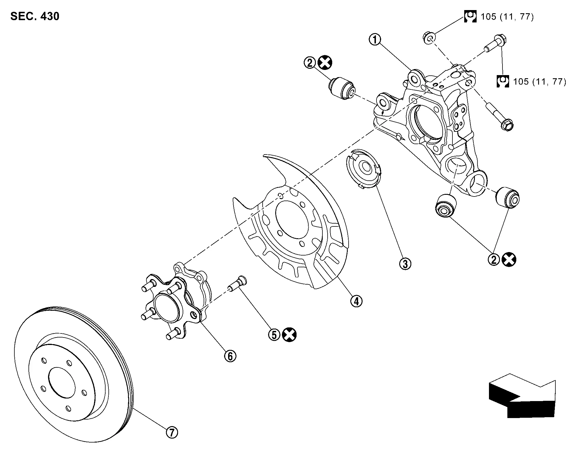
| 1. | Axle housing | 2. | Bushing | 3. | Hub cap |
| 4. | Back plate | 5. | Hub bolt | 6. | Wheel hub and bearing assembly |
| 7. | Disc rotor | тАФ | тАФ | тАФ | тАФ |
| : Nissan Ariya Vehicle front | тАФ | тАФ | тАФ | тАФ | |
 |
: N┬╖m (kg-m, ft-lb) | тАФ | тАФ | тАФ | тАФ |
 |
: Always replace after every disassembly. | ||||
Removal and Installation
REMOVAL
Remove wheel and tire. Refer to Removal & Installation.
Remove parking brake actuator harness and rear wheel sensor. Hang parking brake actuator harness and rear wheel sensor not to interfere with work. Refer to Exploded View.
Remove caliper assembly. Hang caliper assembly in a place where it will not interfere with work. Refer to Removal and Installation.
CAUTION:
Never depress brake pedal while brake caliper is removed.
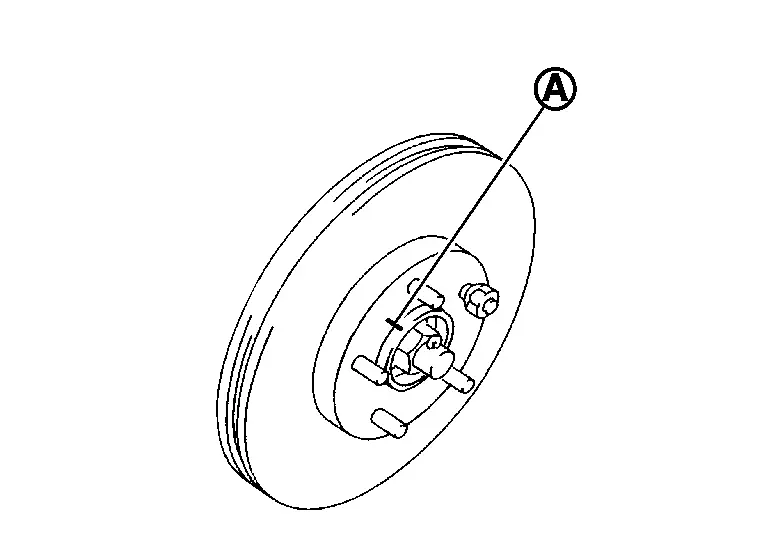
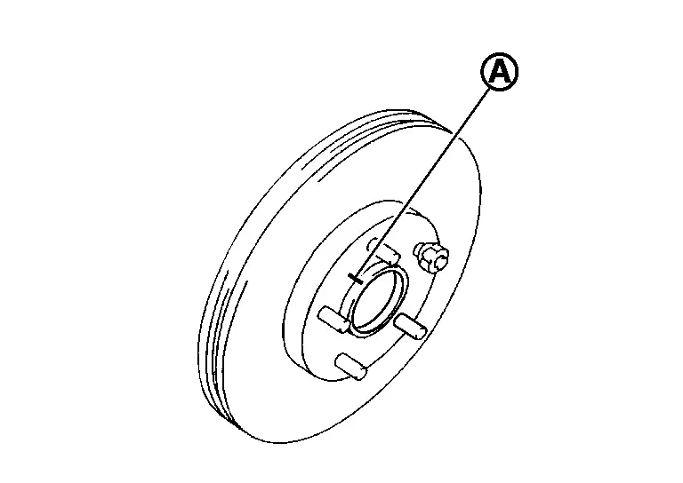
Remove disc rotor.
CAUTION:
-
Put matching marks (A) on the wheel hub and bearing assembly and the disc rotor before removing the disc rotor.
-
Never drop disc rotor.
Remove wheel hub and bearing assembly mounting bolts (A) .
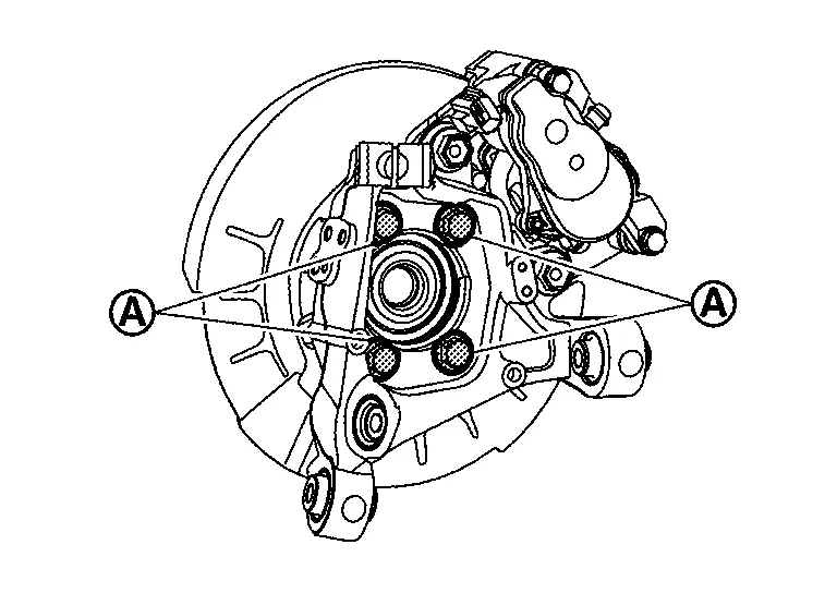
Remove wheel hub and bearing assembly and back plate.
Remove radius rod. Refer to Removal and Installation.
Remove front lower link. Refer to Removal and Installation.
Remove coil spring. Refer to Removal and Installation.
Remove the nut, bolt and brake tube brackets from the rear axle housing. Refer to Exploded View.
Remove rear suspension arm mounting bolts (A) and nuts (B) from axle housing (1).
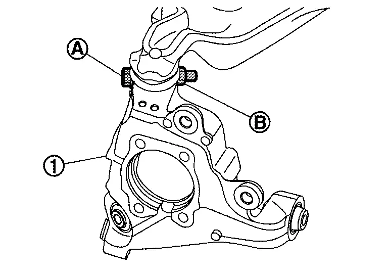
Separate rear suspension arm, and then remove axle housing.
Remove hub bolts (1) from wheel hub and bearing assembly, using the ball joint remover (A) (commercial service tool).
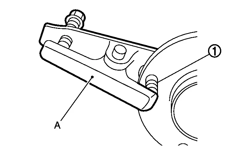
CAUTION:
-
Remove hub bolt only when necessary.
-
Never hammer the hub bolt to avoid impact to the wheel hub and bearing assembly.
-
Pull out the hub bolt in a direction perpendicular to the wheel hub and bearing assembly.
Perform inspection after removal. Refer to Inspection.
INSTALLATION
Note the following, and install in the reverse order of removal.
-
Place a washer (A) as shown in the figure to install the hub bolts (1) by using the tightening force of the nut (B).
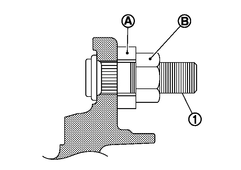
CAUTION:
-
Check that there is no clearance between wheel hub and bearing assembly and hub bolt.
-
Never reuse hub bolt.
-
-
Align the matching marks (A) made during removal when reusing the disc rotor.
-
Perform inspection after installation. Refer to Inspection.
Inspection
INSPECTION AFTER REMOVAL
Check wheel hub and bearing assembly for wear, cracks, and damage. Replace if there are.
INSPECTION AFTER INSTALLATION
Check wheel sensor harness for proper connection. Refer to Exploded View.
If pressing the piston of rear brake caliper assembly, perform "REMOVAL/REPLACEMENT OF REAR BRAKE PAD OR REAR BRAKE CALIPER". Refer to Description.
Check wheel alignment. Refer to Inspection.
Adjust neutral position of steering angle sensor. Refer to Work Procedure.
Other materials:
Intelligent Lane Intervention (I-LI)
Basic information
WARNING
The Intelligent Lane Intervention system on the Nissan Rogue must be used with caution. Ignoring warnings or relying solely on the system may lead to loss of control, injury or death.
I-LI will not steer the Nissan Rogue for you or prevent skidding. The driver must alwa ...
B24a0-49 A/c Auto Amp.
DTC Description
DTC DETECTION LOGIC DTC No.
CONSULT screen terms
(Trouble diagnosis content) DTC detection condition
B24A0-49
A/C AUTO AMP.
(Air conditioning automatic amplifier)
Diagnosis condition
Ignition switch ON
Signal (Terminal)
тАФ
Threshold
A malfunction i ...
Dtc/circuit Diagnosis. Mood Lamp Control Circuit
Component Function Check
CAUTION:
Before performing the diagnosis, check that the following are normal:
Interior room lamp power supply circuit
Mood lamp (center console) bulb (with ambient lighting)
CHECK MOOD LAMP OPERATION
CONSULT
Open the front door LH.
Ignition switc ...