Nissan Rogue Service Manual: Wiring diagram
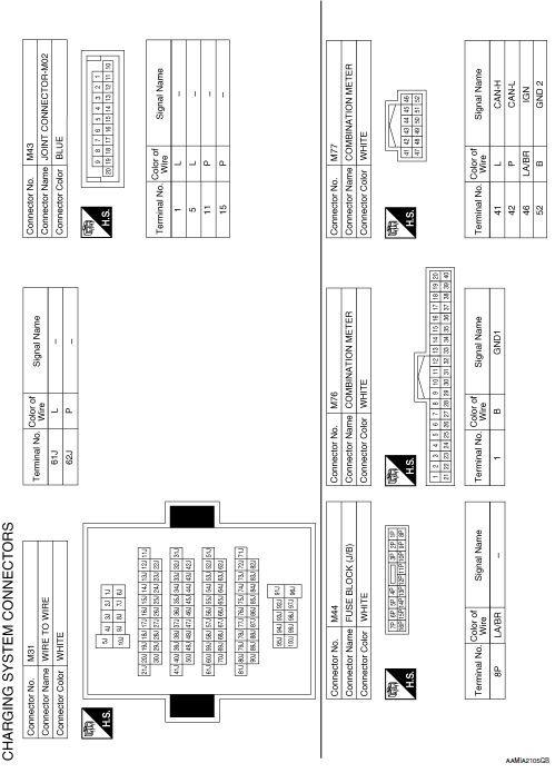
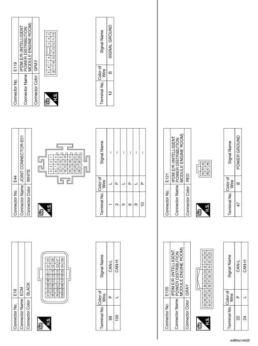
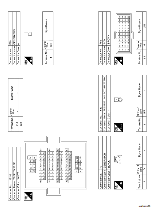
CHARGING SYSTEM
Wiring Diagram


 System
CHARGING SYSTEM
CHARGING SYSTEM : System Description
The generator provides DC voltage to operate the vehicle's electrical system
and to keep the battery charged.
The voltage output is cont ...
 Basic inspection
DIAGNOSIS AND REPAIR WORKFLOW
Work Flow (With EXP-800 NI or GR8-1200 NI)
CHARGING SYSTEM DIAGNOSIS WITH EXP-800 NI OR GR8-1200 NI
To test the charging system, use the following special service tool ...
Other materials:
Periodic maintenance
TRANSFER OIL
Inspection
TRANSFER OIL LEAKS
Check that transfer oil is not leaking from transfer assembly or around it.
TRANSFER OIL LEVEL
CAUTION:
Do not start engine while checking transfer oil level.
Remove filler plug (1) and gasket.
: Front
Transfer oil level (A) should be l ...
Precaution
Precaution for Supplemental Restraint System (SRS) "AIR BAG" and "SEAT
BELT
PRE-TENSIONER"
The Supplemental Restraint System such as “AIR BAG” and “SEAT BELT PRE-TENSIONER”,
used along
with a front seat belt, helps to reduce the risk or severity of injury to the
...
Car phone or CB radio
When installing a CB, ham radio or car phone in
your vehicle, be sure to observe the following
precautions; otherwise, the new equipment may
adversely affect the engine control system and
other electronic parts.
WARNING
A cellular phone should not be used for
any purpose wh ...
