Nissan Rogue Service Manual: System
CHARGING SYSTEM
CHARGING SYSTEM : System Description
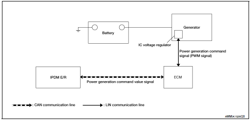
The generator provides DC voltage to operate the vehicle's electrical system and to keep the battery charged.
The voltage output is controlled by the IC regulator.
SYSTEM DIAGRAM

POWER GENERATION VOLTAGE VARIABLE CONTROL SYSTEM
POWER GENERATION VOLTAGE VARIABLE CONTROL SYSTEM : System Description
ECM transmits a target power generation voltage signal received from IPDM E/R to the generator via LIN communication.
The generator includes a self-diagnosis function and transmits a diagnosis signal to ECM via LIN communication when detecting a malfunction. When ECM receives a diagnosis signal, ECM detects DTC and transmits a charge warning lamp request signal to the combination meter to turn ON the charge warning lamp.
SYSTEM DIAGRAM

 Component parts
Component Parts Location
Combination meter
Engine room right side
Engine room left side
No.
Component part
Description
1
Combination meter (Charge ...
 Wiring diagram
CHARGING SYSTEM
Wiring Diagram
...
Other materials:
Instrument panel assembly
Exploded View
Defroster grille
Center speaker grille (if equipped)
Side ventilator grille (LH)
Instrument side finisher (LH)
Knee protector
Instrument finisher A
Cluster lid A
Instrument finisher B (without pushbutton
ignition)
Instrument finishe ...
Wheel and tire
Exploded View
Wheel and tire
Wheel nut
Removal and Installation
REMOVAL
Remove wheel nuts using power tool.
Remove wheel and tire.
INSTALLATION
Installation is in the reverse order of removal.
CAUTION:
When installing wheel nuts, tighten them dia ...
Door outside molding
Exploded View
Front door panel
Front door outside molding
Rear door panel
Rear door outside molding
Pawl
Removal and Installation
FRONT DOOR OUTSIDE MOLDING
Removal
Lower front door glass.
Remove door mirror. Refer to MIR-22, "Removal and Installa ...
