Nissan Rogue Service Manual: Component parts
Component Parts Location
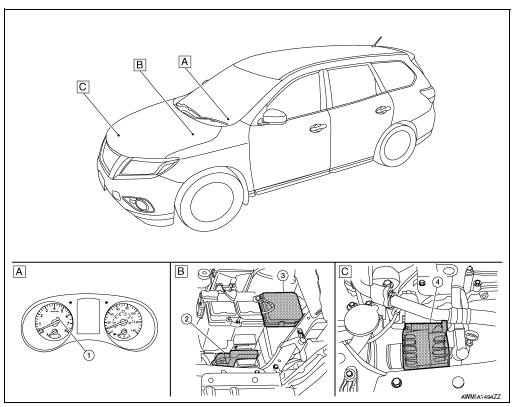
- Combination meter
- Engine room right side
- Engine room left side
|
No. |
Component part |
Description |
| 1 | Combination meter (Charge warning lamp) | The IC regulator warning function activates to illuminate the charge
warning
lamp if any of the following symptoms occur while generator is
operating:
|
| 2 | ECM | ECM transmits a target power generation voltage signal received from IPDM E/R to the generator via LIN communication. In addition, the ECM controls the charge warning lamp via CAN communication to the combination meter. |
| 3 | IPDM E/R | The IPDM E/R receives the generator signals via CAN communication from ECM. |
| 4 | Generator (IC voltage regulator) | IC voltage regulator controls the power generation voltage by the
target
power generation voltage based on the received signal.
When there is no power generation command signal, the generator performs the normal power generation according to the characteristic of the IC voltage regulator. |

 System
CHARGING SYSTEM
CHARGING SYSTEM : System Description
The generator provides DC voltage to operate the vehicle's electrical system
and to keep the battery charged.
The voltage output is cont ...
Other materials:
P0848 transmission fluid pressure SEN/SW B
DTC Description
DTC DETECTION LOGIC
DTC
CONSULT screen terms
(Trouble diagnosis content)
DTC detection condition
P0848
FLUID PRESS SEN/SW B
(Transmission Fluid Pressure Sensor/Switch B
Circuit Low)
When all of the following conditions are satisfied and this sta ...
Emission control system warranty
Your NISSAN vehicle is covered by the following
emission warranties:
For USA
Emission Defects Warranty
Emissions Performance Warranty
Details of this warranty may be found with other
vehicle warranties in your Warranty Information
Booklet which comes with your NISSAN vehicle ...
Easy fill tire alert does not activate
Description
The easy fill tire alert does not function while inflating a tire when the
select lever position is in P-range with the
power switch ON or with the vehicle set to READY.
NOTE:
After starting to inflate the tire, it takes a few seconds for
the easy fill tire alert to fun ...
