Nissan Rogue Service Manual: Instrument panel assembly
Exploded View
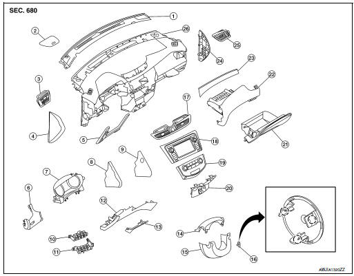
- Defroster grille
- Center speaker grille (if equipped)
- Side ventilator grille (LH)
- Instrument side finisher (LH)
- Knee protector
- Instrument finisher A
- Cluster lid A
- Instrument finisher B (without pushbutton ignition)
- Instrument finisher B (with pushbutton ignition)
- Upper switch carrier
- Lower switch carrier
- Instrument lower panel LH
- Data link cover
- Steering column upper cover
- Steering column lower cover
- Steering lock escutcheon
- Center ventilator grille
- Audio unit (DISPLAY AUDIO) / AV control unit (NAVIGATION WITHOUT BOSE) (NAVIGATION WITH BOSE)
- A/C switch assembly (AUTOMATIC AIR CONDITONING) / front air control (MANUAL AIR CONDITIONING)
- Cluster lid C
- Glove box assembly
- Glove box housing
- Instrument finisher E
- Instrument side finisher (RH)
- Side ventilator grille (RH)
- Instrument panel
INSTRUMENT PANEL ASSEMBLY
INSTRUMENT PANEL ASSEMBLY : Removal and Installation
CAUTION:
- Be careful not to scratch instrument panel pad and other parts.
- Whenever a suitable tool is used, always wrap a cloth around the end of the tool to protect components from damage.
- Before servicing, turn ignition switch OFF, disconnect both battery terminals then wait at least three minutes.
REMOVAL
- Disconnect the negative and positive battery terminals, then wait at least three minutes. Refer to PG-75, "Removal and Installation (Battery)".
- Remove dash side finishers (LH/RH). Refer to INT-24, "DASH SIDE FINISHER : Removal and Installation".
- Remove front pillar finishers (LH/RH). Refer to INT-20, "FRONT PILLAR FINISHER : Removal and Installation".
- Remove combination switch. Refer to EXL-124, "Removal and Installation".
- Remove center console assembly. Refer to IP-18, "Removal and Installation".
- Remove combination meter. Refer to MWI-82, "Removal and Installation".
- Remove audio unit (DISPLAY AUDIO). Refer to AV-64, "Removal and Installation".
- Remove AV control unit. Refer to AV-209, "Removal and Installation" (NAVIGATION WITHOUT BOSE) or AV-376, "Removal and Installation" (NAVIGATION WITH BOSE).
- Remove instrument finisher A. Refer to IP-15, "INSTRUMENT FINISHER A : Removal and Installation".
- Remove instrument finisher B. Refer to IP-16, "INSTRUMENT FINISHER B : Removal and Installation".
- Remove instrument finisher E. Refer to IP-16, "INSTRUMENT FINISHER E : Removal and Installation".
- Remove glove box assembly and housing. Refer to IP-23, "Removal and Installation".
- Remove instrument panel assembly screws.
- Disconnect the harness connectors from the instrument panel assembly and remove.
INSTALLATION
Installation is in the reverse order of removal.
- If replacing the instrument panel, transfer all the necessary parts to the new instrument panel.
INSTRUMENT FINISHER A
INSTRUMENT FINISHER A : Removal and Installation
REMOVAL
- Remove side ventilator grille (LH). Refer to VTL-13, "SIDE VENTILATOR GRILLE : Removal and Installation".
- Remove instrument lower panel LH. Refer to IP-22, "Removal and Installation".
- Release the instrument finisher A clips and pawls using a suitable tool.
 : Pawl
 : Metal clip
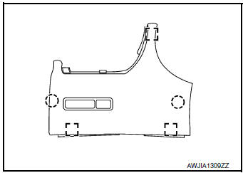
- Disconnect the harness connector from instrument finisher A and remove.
INSTALLATION
Installation is in the reverse order of removal.
INSTRUMENT FINISHER B
INSTRUMENT FINISHER B : Removal and Installation
REMOVAL
- Remove front air control or A/C switch assembly. Refer to HAC-181, "Removal and Installation" (MANUAL AIR CONDITIONING) or HAC-102, "Removal and Installation" (AUTOMATIC AIR CONDITIONING).
- Release the instrument finisher B clips and pawls using a suitable tool.
 : Pawl
 : Metal clip
- Disconnect the harness connector (if equipped) and remove instrument finisher B.
INSTALLATION
Installation is in the reverse order of removal.
INSTRUMENT FINISHER E
INSTRUMENT FINISHER E : Removal and Installation
REMOVAL
- Remove side ventilator grille (RH). Refer to VTL-13, "SIDE VENTILATOR GRILLE : Removal and Installation".
- Release the clips and pawls using a suitable tool and remove instrument finisher E.
Pawl
: Metal clip
INSTALLATION
Installation is in the reverse order of removal

 Steering column covers
Removal and Installation
REMOVAL
Release gap hider (1) pawls from the steering column upper
cover (2).
: Pawl
Remove steering column cover screws (A)
NOTE:
Rotate steering w ...
Other materials:
Basic inspection
INSPECTION AND ADJUSTMENT
ADDITIONAL SERVICE WHEN REPLACING CONTROL UNIT (BCM)
ADDITIONAL SERVICE WHEN REPLACING CONTROL UNIT (BCM) : Description
BEFORE REPLACEMENT
When replacing BCM, save or print current vehicle specification with CONSULT
configuration before replacement.
NOTE:
If “Befo ...
P0441 EVAP control system
DTC Description
DTC DETECTION LOGIC
In this evaporative emission (EVAP) control system, purge flow occurs during
non-closed throttle conditions.
Purge volume is related to air intake volume. Under normal purge conditions
(non-closed throttle), the EVAP
canister purge volume control solenoi ...
Circuit inspection
DESCRIPTION
In general, testing electrical circuits is an easy task if it is
approached in a logical and organized method.
Before beginning it is important to have all available information on the
system to be tested. Also, get a thorough
understanding of system operation. Then y ...
