Nissan Rogue Service Manual: Circuit inspection
DESCRIPTION
- In general, testing electrical circuits is an easy task if it is
approached in a logical and organized method.
Before beginning it is important to have all available information on the system to be tested. Also, get a thorough understanding of system operation. Then you will be able to use the appropriate equipment and follow the correct test procedure.
- You may have to simulate vehicle vibrations while testing electrical components. Gently shake the wiring harness or electrical component to do this.
| OPEN | A circuit is open when there is no continuity through a section of the circuit. | |
| SHORT | There are two types of shorts. | |
|
When a circuit contacts another circuit and causes the normal resistance to change. | |
|
When a circuit contacts a ground source and grounds the circuit. | |
NOTE: Refer to GI-38, "How to Check Terminal" to probe or check terminal.
TESTING FOR ÔÇťOPENSÔÇŁ IN THE CIRCUIT
Before you begin to diagnose and test the system, you should rough sketch a schematic of the system. This will help you to logically walk through the diagnosis process. Drawing the sketch will also reinforce your working knowledge of the system.
Continuity Check Method
The continuity check is used to find an open in the circuit. The digital multimeter (DMM) set on the resistance function will indicate an open circuit as over limit (no beep tone or no ohms symbol). Make sure to always start with the DMM at the highest resistance level.
To help in understanding the diagnosis of open circuits, please refer to the previous schematic.
- Disconnect the battery negative cable.
- Start at one end of the circuit and work your way to the other end. (At the fuse block in this example)
- Connect one probe of the DMM to the fuse block terminal on the load side.
- Connect the other probe to the fuse block (power) side of SW1. Little or no resistance will indicate that portion of the circuit has good continuity. If there were an open in the circuit, the DMM would indicate an over limit or infinite resistance condition. (point A)
- Connect the probes between SW1 and the relay. Little or no resistance will indicate that portion of the circuit has good continuity. If there were an open in the circuit, the DMM would indicate an over limit or infinite resistance condition. (point B)
- Connect the probes between the relay and the solenoid. Little or no resistance will indicate that portion of the circuit has good continuity. If there were an open in the circuit, the DMM would indicate an over limit or infinite resistance condition. (point C)
Any circuit can be diagnosed using the approach in the previous example.
Voltage Check Method
To help in understanding the diagnosis of open circuits please refer to the previous schematic.
In any powered circuit, an open can be found by methodically checking the system for the presence of voltage.
This is done by switching the DMM to the voltage function.
- Connect one probe of the DMM to a known good ground.
- Begin probing at one end of the circuit and work your way to the other end.
- With SW1 open, probe at SW1 to check for voltage.
Voltage; open is further down the circuit than SW1. no voltage; open is between fuse block and SW1 (point A).
- Close SW1 and probe at relay.
Voltage; open is further down the circuit than the relay.
No voltage; open is between SW1 and relay (point B).
- Close the relay and probe at the solenoid.
Voltage; open is further down the circuit than the solenoid.
No voltage; open is between relay and solenoid (point C).
Any powered circuit can be diagnosed using the approach in the previous example.
TESTING FOR ÔÇťSHORTSÔÇŁ IN THE CIRCUIT
To simplify the discussion of shorts in the system, please refer to the following schematic.
Resistance Check Method
- Disconnect the battery negative cable and remove the blown fuse.
- Disconnect all loads (SW1 open, relay disconnected and solenoid disconnected) powered through the fuse.
- Connect one probe of the DMM to the load side of the fuse terminal. Connect the other probe to a known good ground.
- With SW1 open, check for continuity.
Continuity; short is between fuse terminal and SW1 (point A).
No continuity; short is further down the circuit than SW1.
- Close SW1 and disconnect the relay. Put probes at the load side of
fuse terminal and a known good ground.
Then, check for continuity.
Continuity; short is between SW1 and the relay (point B).
No continuity; short is further down the circuit than the relay.
- Close SW1 and jump the relay contacts with jumper wire. Put probes
at the load side of fuse terminal and a
known good ground. Then, check for continuity.
Continuity; short is between relay and solenoid (point C).
No continuity; check solenoid, retrace steps.
Voltage Check Method
- Remove the blown fuse and disconnect all loads (i.e. SW1 open, relay disconnected and solenoid disconnected) powered through the fuse.
- Turn the ignition key to the ON or START position. Verify battery voltage at the battery + side of the fuse terminal (one lead on the battery + terminal side of the fuse block and one lead on a known good ground).
- With SW1 open and the DMM leads across both fuse terminals, check
for voltage.
Voltage; short is between fuse block and SW1 (point A).
No voltage; short is further down the circuit than SW1.
- With SW1 closed, relay and solenoid disconnected and the DMM leads
across both fuse terminals, check for
voltage.
Voltage; short is between SW1 and the relay (point B).
No voltage; short is further down the circuit than the relay.
- With SW1 closed, relay contacts jumped with fused jumper wire
check for voltage.
Voltage; short is down the circuit of the relay or between the relay and the disconnected solenoid (point C).
No voltage; retrace steps and check power to fuse block.
GROUND INSPECTION
- Ground connections are very important to the proper operation of electrical and electronic circuits. Ground connections are often exposed to moisture, dirt and other corrosive elements. The corrosion (rust) can become an unwanted resistance. This unwanted resistance can change the way a circuit works.
- Electronically controlled circuits are very sensitive to proper
grounding. A loose or corroded ground can
drastically affect an electronically controlled circuit. A poor or corroded
ground can easily affect the circuit.
Even when the ground connection looks clean, there can be a thin film of rust on the surface.
- When inspecting a ground connection follow these rules:
- Remove the ground bolt or screw.
- Inspect all mating surfaces for tarnish, dirt, rust, etc.
- Clean as required to assure good contact.
- Reinstall bolt or screw securely.
- Inspect for ÔÇťadd-onÔÇŁ accessories which may be interfering with the ground circuit.
- If several wires are crimped into one ground eyelet terminal, check for proper crimps. Make sure all of the wires are clean, securely fastened and providing a good ground path. If multiple wires are cased in one eyelet make sure no ground wires have excess wire insulation.
-
For detailed ground distribution information, refer to ÔÇťGround DistributionÔÇŁ in PG section.
-
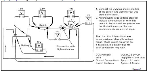
VOLTAGE DROP TESTS
- Voltage drop tests are often used to find components or circuits which have excessive resistance. A voltage drop in a circuit is caused by a resistance when the circuit is in operation.
- Check the wire in the illustration. When measuring resistance with DMM, contact by a single strand of wire will give reading of 0 ohms. This would indicate a good circuit. When the circuit operates, this single strand of wire is not able to carry the current. The single strand will have a high resistance to the current. This will be picked up as a slight voltage drop.
- Unwanted resistance can be caused by many situations as follows:
- Undersized wiring (single strand example)
- Corrosion on switch contacts
- Loose wire connections or splices.
- If repairs are needed always use wire that is of the same or larger gauge.
Measuring Voltage Drop ÔÇö Accumulated Method
- Connect the DMM across the connector or part of the circuit you want to check. The positive lead of the DMM should be closer to power and the negative lead closer to ground.
- Operate the circuit.
- The DMM will indicate how many volts are being used to ÔÇťpushÔÇŁ current through that part of the circuit.
Note in the illustration that there is an excessive 4.1 volt drop between the battery and the bulb.
Measuring Voltage Drop ÔÇö Step-by-Step
- The step-by-step method is most useful for isolating excessive drops in low voltage systems (such as those in ÔÇťComputer Controlled SystemsÔÇŁ).
- Circuits in the ÔÇťComputer Controlled SystemÔÇŁ operate on very low amperage.
- The (Computer Controlled) system operations can be adversely affected by any variation in resistance in the system. Such resistance variation may be caused by poor connection, improper installation, improper wire gauge or corrosion.
- The step by step voltage drop test can identify a component or wire with too much resistance.
CONTROL UNIT CIRCUIT TEST
System Description
- When the switch is ON, the control unit lights up the lamp.
CASE 1
INPUT-OUTPUT VOLTAGE CHART
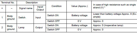
- The voltage value is based on the body ground.
- *: If high resistance exists in the switch side circuit (caused by a single strand), terminal 1 does not detect battery voltage. Control unit does not detect the switch is ON even if the switch does not turn ON. Therefore, the control unit does not supply power to light up the lamp.
CASE 2
INPUT-OUTPUT VOLTAGE CHART
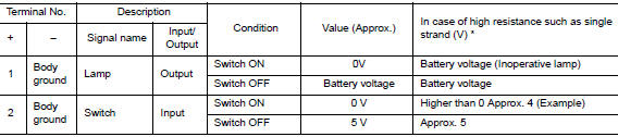
- The voltage value is based on the body ground.
- *: If high resistance exists in the switch side circuit (caused by a single strand), terminal 2 does not detect approx. 0V. Control unit does not detect the switch is ON even if the switch does not turn ON. Therefore, the control unit does not control ground to light up the lamp.
 Intermittent incident
DESCRIPTION
Sometimes the symptom is not present when the vehicle is brought in for
service. If possible, re-create the
conditions present at the time of the incident. Doing so may help avoid a No ...
 Consult/gst checking system
Description
NOTE:
This vehicle is diagnosed using the CONSULT-III plus.
When CONSULT is connected with a data link connector equipped
on the vehicle side, it will communicate with the co ...
Other materials:
P0116 ECT sensor
DTC Description
DTC DETECTION LOGIC
DTC No.
CONSULT screen terms
(Trouble diagnosis content)
DTC detecting condition
P0116
ECT SENSOR
(Engine coolant temperature sensor 1 circuit
range/performance)
The comparison result of signals transmitted to ECM from each
...
Symptom diagnosis
SQUEAK AND RATTLE TROUBLE DIAGNOSES
Work Flow
CUSTOMER INTERVIEW
Interview the customer if possible, to determine the conditions that exist
when the noise occurs. Use the Diagnostic
Worksheet during the interview to document the facts and conditions when the
noise occurs and any
custome ...
Diagnosis system (air bag)
Description
CAUTION:
Never use electrical test equipment on any circuit related to
the SRS unless instructed in this Service
Manual. SRS wiring harnesses can be identified by yellow and/or orange
harnesses or harness
connectors.
Never repair, splice or modify the SRS wir ...
