Nissan Rogue Service Manual: Consult/gst checking system
Description
NOTE: This vehicle is diagnosed using the CONSULT-III plus.
- When CONSULT is connected with a data link connector equipped on the vehicle side, it will communicate with the control unit equipped in the vehicle and then enable various kinds of diagnostic tests.
- Hood release handle
- Data link connector
- Refer to “CONSULT-III plus Operation Manual” for more information.
Function and System Application
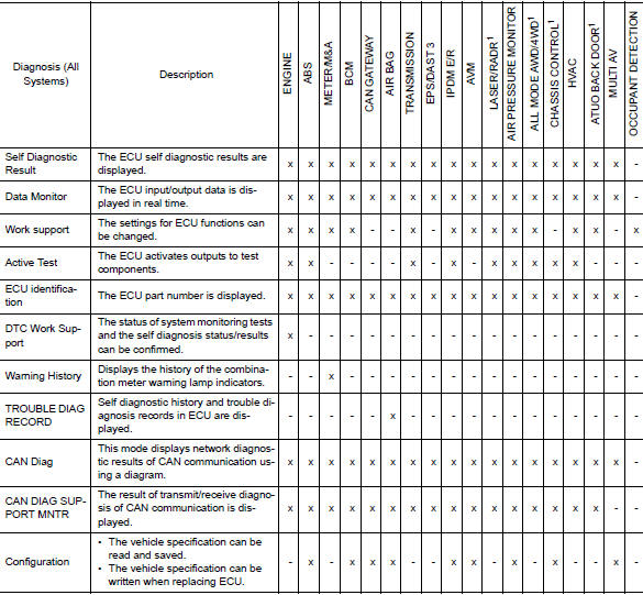
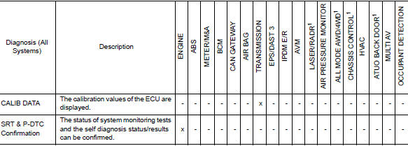
x: Applicable
1: If equipped
CONSULT Data Link Connector (DLC) Circuit
INSPECTION PROCEDURE
If the CONSULT cannot diagnose the system properly, check the following items.
| Symptom | Check item |
| CONSULT cannot access any system. |
|
| CONSULT cannot access individual system. (Other systems can be accessed.) |
|
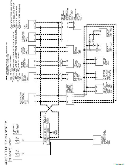
NOTE: The DDL2 circuits and CAN communication lines from DLC pins 6, 7 and 14 may be connected to more than one system. A short in a DDL circuit or CAN lines connected to a control unit in one system may affect CONSULT access to other systems. For a complete DDL circuit layout, refer to GI-51, "Wiring Diagram - CONSULT/ GST CHECKING SYSTEM". For a complete CAN line layout, refer to LAN-35, "Wiring Diagram - CAN SYSTEM -".
Wiring Diagram - CONSULT/GST CHECKING SYSTEM
 Circuit inspection
DESCRIPTION
In general, testing electrical circuits is an easy task if it is
approached in a logical and organized method.
Before beginning it is important to have all available informa ...
 Engine
...
Other materials:
Air conditioner system refrigerant and oil recommendations
The air conditioner system in your NISSAN
vehicle must be charged with the refrigerant
HFC-134a (R-134a) and NISSAN A/C
system oil Type ND-OIL8 or the exact
equivalents.
CAUTIONThe use of any other refrigerant or oil will
cause severe damage to the air conditioning
system and will ...
Removal and installation
ACCELERATOR PEDAL ASSEMBLY
Exploded View
Brake pedal
Accelerator pedal assembly
Locator hook
Locator pin
Bolt
Removal and Installation
REMOVAL
Disconnect the harness connector from the accelerator pedal
assembly.
Remove the bolts, then rem ...
P0506 ISC system
Description
The ECM controls the engine idle speed to a specified level through the fine
adjustment of the air, which is let
into the intake manifold, by operating the electric throttle control actuator.
The operating of the throttle valve is
varied to allow for optimum control of the engine ...
