Nissan Rogue Service Manual: Removal and installation
ACCELERATOR PEDAL ASSEMBLY
Exploded View
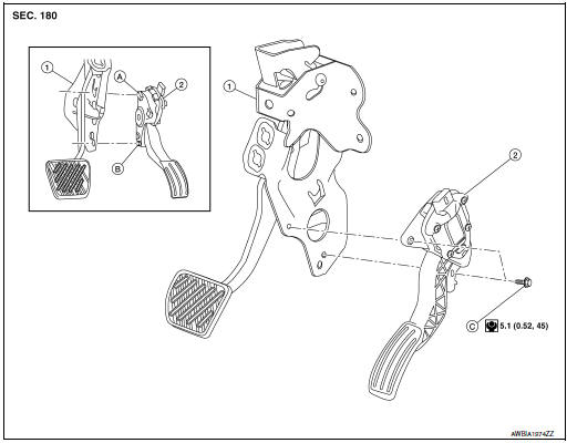
- Brake pedal
- Accelerator pedal assembly
- Locator hook
- Locator pin
- Bolt
Removal and Installation
REMOVAL
- Disconnect the harness connector from the accelerator pedal assembly.
- Remove the bolts, then remove accelerator pedal assembly.
CAUTION:
- Do not disassemble accelerator pedal assembly.
- Do not drop or impact accelerator pedal assembly.
- Do not expose accelerator pedal assembly to water.
INSTALLATION
Installation is in the reverse order of removal.
NOTE: When installing the accelerator pedal assembly, make sure to align locator hook and locator pin before installing bolts.
For inspection, refer to ACC-3, "Inspection".
Inspection
INSPECTION AFTER INSTALLATION
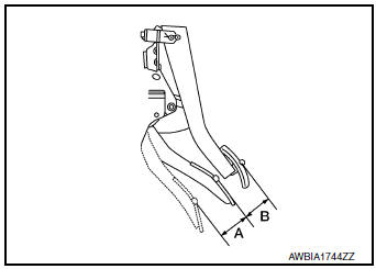
- Check that the accelerator pedal moves smoothly within the specified range.
Accelerator pedal stroke (A) : Refer to ACC-5, "Accelerator Control"
- Check the accelerator pedal height.
Accelerator pedal height (B) : Refer to ACC-5, "Accelerator Control"
- accelerator pedal does not meet specified values, check brake pedal height. Refer to ACC-3, "Inspection".
- Depress and release the accelerator pedal to check that it returns quickly and smoothly to the original released position.
CAUTION:
- Whenever the harness connector of the accelerator pedal position sensor has been disconnected, perform "Accelerator Pedal Released Position Learning". Refer to EC-139, "Work Procedure".
- The accelerator pedal should operate smoothly without catching when the pedal operating force is released. The pedal should return smoothly to the fully raised position. The spring should be free from damage.
 Precaution
Precaution for Supplemental Restraint System (SRS) "AIR BAG" and "SEAT
BELT
PRE-TENSIONER"
The Supplemental Restraint System such as ŌĆ£AIR BAGŌĆØ and ŌĆ£SEAT BELT PRE-TENSIONE ...
 Service data and specifications
(SDS)
Service data and specifications
(SDS)
Accelerator Control
Accelerator pedal stroke (A)
49.6 - 52.4 (1.95 - 2.06
Pedal height difference between accelerator and brake (B)
35 - 45 (1.38 - 1.77)
...
Other materials:
Cluster lid C
Exploded View
Audio unit (AUDIO WITHOUT BOSE) /
AV control unit (AUDIO WITH BOSE)
(NAVIGATION WITH BOSE)
A/C switch assembly (AUTOMATIC
AIR CONDITIONING) / front air control
(MANUAL AIR CONDITIONING)
Cluster lid C
Removal and Installation
REMOVAL
Release ...
Rear disc brake
BRAKE PAD
BRAKE PAD : Exploded View
Sliding pin bolt
Sliding pin bushing
Cylinder body
Inner shim cover
Inner shim
Inner pad
Pad retainer
Torque member
Outer pad
Outer shim
Outer shim cover
Molykote AS-880N
Niglube Rx-2
BRAKE PAD : Re ...
Remote keyless entry (if so equipped)
CAUTIONDo not leave the ignition key inside the
vehicle when you leave the vehicle.
key number plate is supplied with your keys.
Record the key number and keep it in a safe place
(such as your wallet), not in the vehicle. If you lose
your keys, see a NISSAN dealer for duplicates ...
