Nissan Rogue Service Manual: Diagnosis system (air bag)
Description
CAUTION:
- Never use electrical test equipment on any circuit related to the SRS unless instructed in this Service Manual. SRS wiring harnesses can be identified by yellow and/or orange harnesses or harness connectors.
- Never repair, splice or modify the SRS wiring harness. If the harness is damaged, replace it with a new one.
- Keep ground portion clean.
DIAGNOSIS FUNCTION
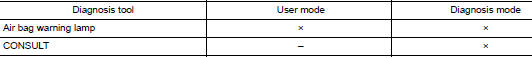
- The SRS self-diagnostic results can be read with air bag warning lamp and/or CONSULT.
- The user mode is exclusively prepared for the customer (driver). This mode warns the driver of a system malfunction through the operation of the air bag warning lamp.
- The diagnosis mode allows the technician to locate and inspect the malfunctioning part.
- The mode applications for the air bag warning lamp and CONSULT are as per the following items.
On Board Diagnosis Function
ON-BOARD DIAGNOSIS
There are two self diagnosis functions with air bag warning lamp per the following items.
- USER MODE
- DIAGNOSIS MODE
METHOD OF STARTING
- Diagnosis mode changes from user mode to diagnosis mode when changing operation is performed.
- In user mode, when SRS air bag warning lamp is not turning ON, changing to diagnosis mode by ignition switch operation is not possible.
- In diagnosis mode, when repair is complete and system is normal, the mode changes to user mode when ignition switch is turned from OFF to ON.
Procedure to Change Diagnosis Mode
- Turn ignition switch from OFF to ON.
- SRS air bag lamp turns ON for 7 seconds and turns OFF, then turn
ignition switch OFF within 2 seconds
after the lamp turns OFF.
NOTE: When in Diagnosis Mode, the air bag warning lamp may illuminate for more than 7 seconds after the ignition switch is turned ON. If this is the case, the ignition switch must still be cycled OFF after 7 seconds.
- After turning ignition switch OFF, wait for 3 seconds or more.
- Repeat operation 1 to 3 for 2 times so that operation 1 to 3 is repeated for 3 times in total.
- Turn ignition switch from OFF to ON. Diagnosis mode changes.
USER MODE
In USER MODE, air bag warning lamp on combination meter turns ON when a malfunction is detected and warns the customer (driver).
How to Read Air Bag Warning Lamp
- Turn the ignition switch from OFF to ON, and check that the air bag warning lamp turns ON.
- Compare the air bag warning lamp operation pattern with the examples.
Air Bag Warning Lamp Examples:
Air bag warning lamp flashing pattern (User Mode)
|
Warning lamp |
SRS condition |
Reference item |
|
|
|
— |
|
|
The system is malfunctioning and needs to be repaired. | Refer to SRC-18, "Trouble Diagnosis with CONSULT" or SRC-16, "On Board Diagnosis Function". |
|
|
|
Refer to Frontal collision: SR-5, "FOR FRONTAL COLLISION : When SRS is activated in a collision", SR-6, "FOR FRONTAL COLLISION : When SRS is not activated in a collision" or Side and rollover collision: SR-7, "FOR SIDE AND ROLLOVER COLLISION : When SRS is activated in a collision", SR- 8, "FOR SIDE AND ROLLOVER COLLISION : When SRS is not activated in a collision". |
|
Refer to SRC-99, "AIR BAG Warning Lamp Does Not Turn Off". | |
|
|
|
Refer to SRC-98, "AIR BAG Warning Lamp Does Not Turn On". |
DIAGNOSIS MODE
NOTE: Diagnosis Mode can not be entered if a malfunction is not detected in User Mode.
- Turn ignition switch ON.
- After AIR BAG warning lamp lights for 7 seconds, turn ignition switch OFF within 1 second.
- Wait more than 3 seconds.
- Repeat steps 1 to 3 two more times (3 times total).
- Turn ignition switch ON.
SRS is now in Diagnosis Mode. Refer to SRC-23, "Flash Code Index".
Trouble Diagnosis with CONSULT
- Connect CONSULT.
- DTC is displayed on SELF-DIAG RESULTS.
NOTE: If a malfunction is not detected on SELF-DIAG RESULTS [CURRENT], but a malfunction is detected during
SRS Operation Check, the following cases may exist:
- SELF-DIAG [PAST] memory might not be erased. Refer to SRC-16, "On Board Diagnosis Function".
- SRS system malfunctions intermittently. Refer to SRC-45, "Inspection Procedure".
DIAGNOSIS MODE
- Connect CONSULT.
- Confirm that zero point reset of OCS is complete.
- If no DTCs are detected on “SELF-DIAG RESULTS [CURRENT]”, repair
of SRS is completed. Go to step
4.
If any DTCs are detected on “SELF-DIAG RESULTS [CURRENT]”, the malfunction has not been repaired completely or another malfunction is being detected. Perform SRS Operation Check again. Refer to SRC- 16, "On Board Diagnosis Function".
- Touch “ERASE”.
NOTE: Touching “ERASE” will clear the SRS memory of the malfunction (“SELF-DIAG [PAST]”). If “SELFDIAG [PAST]” is not erased, User Mode may show the previous system malfunction even if the malfunction has been repaired completely.
- Check that no malfunction is detected in “SELF-DIAG [PAST]”.
- Exit Diagnosis Mode and disconnect the CONSULT.
- Perform SRS Operation Check. Refer to SRC-16, "On Board Diagnosis Function".
SRS HISTORY CHECK
- Check repair history of the SRS. If no repairs have been made, perform SRC-16, "On Board Diagnosis Function". If repairs have been made, GO TO step 2.
- Erase ”SELF-DIAG [PAST]” after repair. Refer to SRC-16, "On Board Diagnosis Function".
CONSULT Function (AIR BAG)
CONSULT can display each diagnostic item using the diagnostic test modes shown following.
|
Diagnostic Test Mode |
Diagnostic Item |
Description |
| Self Diagnostic Result | SELF-DIAG RESULT [CURRENT] | A current Self-diagnosis result (also indicated by the number of warning lamp flashes in the Diagnosis mode) is displayed on the CONSULT screen in real time. This refers to a malfunctioning part requiring repairs. |
| Data Monitor | DATA MONITOR | Displays air bag diagnosis sensor unit input/output data in real time. |
| ECU Identification | ECU DISCRIMINATED NO. | Air bag diagnosis sensor unit ECU discriminated number (identification number) or part number is displayed. Air bag diagnosis sensor unit has individual ECU discriminated number (identification number) or part number based on model and equipment. |
| Trouble Diagnostic Record | TROUBLE DIAG RECORD [PAST] | With TROUBLE DIAG RECORD, diagnosis results previously erased by a reset operation can be displayed on the CONSULT screen. |
 System
SRS AIR BAG SYSTEM
SRS AIR BAG SYSTEM : System Description
SYSTEM DIAGRAM
DESCRIPTION
The air bag deploys if the air bag diagnosis sensor unit is
activated while the ignition switc ...
 ECU diagnosis information
DIAGNOSIS SENSOR UNIT
DTC Index
DIAGNOSTIC CODE CHART
NOTE:
Follow the procedures in numerical order when repairing malfunctioning parts.
Confirm whether malfunction is
eliminated using air bag ...
Other materials:
P0605 ECM
DTC Description
DTC DETECTION LOGIC
DTC No.
CONSULT screen terms
(Trouble diagnosis content)
DTC detecting condition
P0605
ECM
[Internal control module read only memory
(ROM) error]
Malfunction in the internal ROM of ECM.
POSSIBLE CAUSE
ECM
FAIL-SAFE
T ...
Removal and installation
FRONT WHEEL HUB
Exploded View
Disc brake rotor
Nut retainer
Cotter pin
Wheel stud
Steering knuckle
Splash guard
Wheel hub and bearing
Wheel hub lock nut
Removal and Installation
REMOVAL
Remove front wheel and tire using power tool. Refe ...
Water pump
Exploded View
Cylinder block
Water pump
Water pump gasket
Water pump housing
O-ring
Water pipe
Water pump housing gasket
Refer to INSTALLATION
Removal and Installation
REMOVAL
Drain engine coolant. Refer to CO-8, "Draini ...
