Nissan Rogue Service Manual: System
SRS AIR BAG SYSTEM
SRS AIR BAG SYSTEM : System Description
SYSTEM DIAGRAM
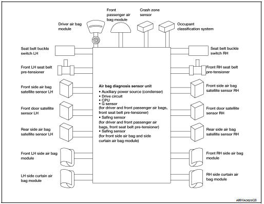
DESCRIPTION
- The air bag deploys if the air bag diagnosis sensor unit is activated while the ignition switch is in the ON or START position.
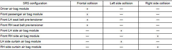
- The collision modes for which supplemental restraint systems are activated are different among the SRS systems. For example, the driver air bag module, front passenger air bag module and front seat belt pre-tensioners are activated in a frontal collision but not in a side collision.
SRS Collision Modes
OCCUPANT CLASSIFICATION SYSTEM
OCCUPANT CLASSIFICATION SYSTEM : System Description
SYSTEM DIAGRAM
DESCRIPTION
The occupant classification system (OCS) identifies different size occupants, out of position occupants, and detects if child seat is present in the front passenger seat. The OCS control unit (2) receives inputs from the occupant classification sensors (1) (located on the passenger seat track assembly). Depending on classification of the passenger, the OCS sends a signal to the air bag diagnosis sensor unit. The air bag diagnosis sensor unit uses this signal and the seat belt buckle switch RH signal to determine deployment or non deployment of the passenger front air bag in the event of a collision. Depending on the signals received, the air bag diagnosis sensor unit can disable the passenger front air bag completely. The OCS (weight sensors) must be set to zero point using CONSULT after servicing the OCS system.
NOTE:
- CONSULT can be used to confirm when “zero point reset” for OCS is complete.
- Always perform zero point reset after the removal and installation of the seat or when disconnecting the OCS control unit harness connector even if zero point reset has been completed in the past.
- If zero point reset is incomplete, the passenger air bag will be disabled and the passenger air bag off indicator will be ON.
- In case of customer concern, CONSULT can be used to confirm the passenger air bag status (readiness).
Passenger Air Bag Status Conditions
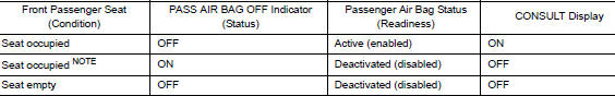
NOTE: Passenger does not meet Occupant Classification System specifications for passenger air bag activation.
SEAT BELT WARNING LAMP SYSTEM
SEAT BELT WARNING LAMP SYSTEM : System Description
SYSTEM DIAGRAM
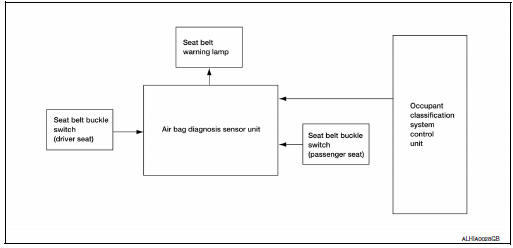
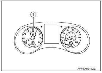
The seat belt warning lamp (1) will remind the driver if the driver or front passenger seat belt should be buckled. The system works in conjunction with the occupant classification system. Refer to SRC- 13, "OCCUPANT CLASSIFICATION SYSTEM : System Description".
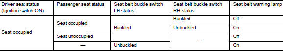
Seat Belt Warning System Operation
 Component parts
Component Parts Location
Instrument panel
View with drivers door finisher removed
View with center console removed
View with the lower B-pillar trim
removed
V ...
 Diagnosis system (air bag)
Description
CAUTION:
Never use electrical test equipment on any circuit related to
the SRS unless instructed in this Service
Manual. SRS wiring harnesses can be identified by yellow an ...
Other materials:
Washer switch
Description
Washer switch is integrated with the combination switch.
Combination switch (wiper and washer switch) switches polarity
between front washer operating and rear
washer operating to supply power and ground to the front and rear washer
motor.
Component Inspection
...
Heater operation
Heating
This mode is used to direct heated air to the foot
outlets. Some air also flows from the defrost
outlets and the side vent outlets.
Press the button to
change to fresh
air intake mode. The indicator
light
will turn off for normal heating.
Press the air flow ...
Meter system
Wiring diagram
...
