Nissan Rogue Service Manual: Component parts
Component Parts Location
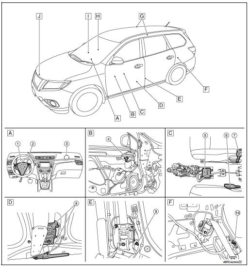
- Instrument panel
- View with drivers door finisher removed
- View with center console removed
- View with the lower B-pillar trim removed
- View with the lower B-pillar trim removed
- View with LH rear lower luggage finisher removed
- View with headlining removed
- RH front passenger seat
- Occupant classification system
- Radiator core support assembly
|
No. |
Component |
Function |
| 1 | Spiral cable | The spiral cable provides a rotating physical connection to the driver air bag module. |
| 2 | Drivers air bag module | Refer to SRC-9, "Driver Air Bag Module". |
| 3 | Front passenger air bag module | Refer to SRC-9, "Front Passenger Air Bag Module". |
| 4 | Front door satellite sensor | Refer to SRC-11, "Front Door Satellite Sensor". |
| 5 | Air bag diagnosis sensor unit | Refer to SRC-10, "Air Bag Diagnosis Sensor Unit". |
| 6 | Seat belt buckle switch (driver seat) | The seat belt buckle switch LH provides the seat belt buckle signals to the air bag diagnosis sensor unit and the combination meter. |
| 7 | Seat belt buckle switch (passenger seat) | The seat belt buckle switch RH provides the seat belt buckle signals to the air bag diagnosis sensor unit and the combination meter. |
| 8 | Front LH seat belt pre-tensioner (RH similar) | Refer to SRC-10, "Front Seat Belt Pre-tensioner". |
| 9 | Front side air bag satellite sensor | Refer to SRC-10, "Front Side Air Bag Satellite Sensor". |
| 10 | Rear side air bag satellite sensor LH (RH similar) | Refer to SRC-11, "Rear Side Air Bag Satellite Sensor". |
| 11 | RH side curtain air bag module (LH similar) | Refer to SRC-9, "Side Curtain Air Bag Module". |
| 12 | Front RH side air bag module (LH similar) | Refer to SRC-9, "Front Side Air Bag Module". |
| 13 | Occupant classification system control unit | Refer to SRC-13, "OCCUPANT CLASSIFICATION SYSTEM : System Description". |
| 14 | Occupant classification system sensors | Refer to SRC-13, "OCCUPANT CLASSIFICATION SYSTEM : System Description". |
| 15 | Crash zone sensor | Refer to SRC-10, "Crash Zone Sensor". |
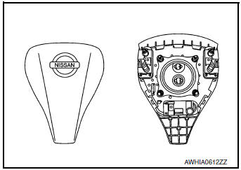
Driver Air Bag Module
The driver air bag module is dual stage and located in the steering wheel assembly. It operates with the SRS system in a frontal collision exceeding a specified level.
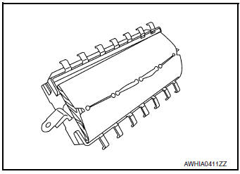
Front Passenger Air Bag Module
The front passenger air bag module is dual stage and is located behind the instrument panel assembly. It operates with the SRS system in a frontal collision exceeding a specified level. Refer to SRC- 12, "SRS AIR BAG SYSTEM : System Description" for more information.
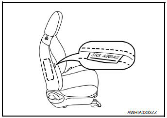
Front Side Air Bag Module
Front side air bag modules are built into the front seatback assemblies.
Vehicles with side air bags are equipped with labels as shown.
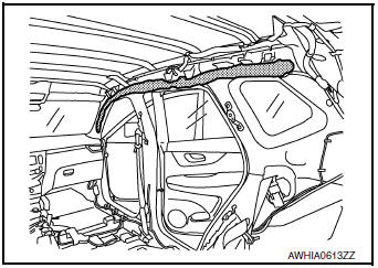
Side Curtain Air Bag Module
Side curtain air bag modules are located above the vehicle headlining.
Vehicles with side curtain air bags are equipped with labels on the pillar upper finishers.
Front Seat Belt Pre-tensioner
The seat belt pre-tensioner system with load limiter is installed for both the driver's seat and the front passenger's seat. It operates simultaneously with the SRS air bag system in the event of a frontal collision with an impact exceeding a specified level.
When the frontal collision with an impact exceeding a specified level occurs, seat belt slack resulting from clothing or other factors is immediately taken up by the shoulder belt pre-tensioner as well as the lap belt pre-tensioner. Vehicle passengers are securely restrained.
When passengers in a vehicle are thrown forward in a collision and the restraining force of the seat belt exceeds a specified level, the load limiter permits the specified extension of the seat belt by the twisting of the ELR shaft, and a relaxation of the chest-area seat belt web tension while maintaining force.
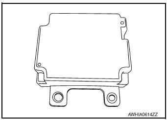
Air Bag Diagnosis Sensor Unit
The air bag diagnosis sensor unit is located under the center console assembly. The air bag diagnosis sensor unit receives signals from multiple SRS sensors and controls the deployment of the air bags. The deployment of the air bags depends on the type and severity of the collision. The air bag diagnosis sensor unit has selfdiagnosis capability through the use of the CONSULT as well as flash codes displayed by the air bag warning lamp.
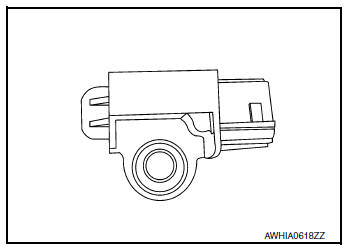
Crash Zone Sensor
The crash zone sensor is located in front of the radiator. The crash zone sensor sends signals to the air bag diagnosis sensor unit during a frontal collision. This sensor may be identified by a yellow connector.
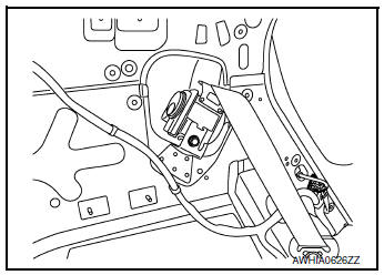
Front Side Air Bag Satellite Sensor
The front side air bag satellite sensors are located on the front center pillar LH and RH next to the seat belt pretensioners. The front side air bag satellite sensors send signals to the air bag diagnosis sensor unit during a side collision. These sensors may be identified by yellow connectors.
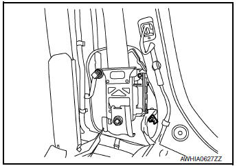
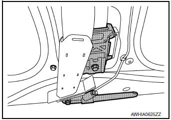
Rear Side Air Bag Satellite Sensor
The rear side air bag satellite sensors are located behind the luggage side lower finisher LH and RH. The rear side air bag satellite sensors send signals to the air bag diagnosis sensor unit during a side collision. These sensors may be identified by yellow connectors.
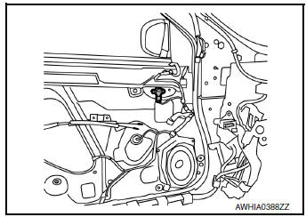
Front Door Satellite Sensor
The front door satellite sensors are located in the driver and passenger doors. The front door satellite sensors send signals to the air bag diagnosis sensor unit during a side collision. These sensors may be identified by yellow connectors.

 System
SRS AIR BAG SYSTEM
SRS AIR BAG SYSTEM : System Description
SYSTEM DIAGRAM
DESCRIPTION
The air bag deploys if the air bag diagnosis sensor unit is
activated while the ignition switc ...
Other materials:
FM/AM radio with compact disc (CD) player
(if so equipped)
FM/AM radio with compact disc (CD) player
CD eject button
CD button
Display screen
CD insert slot
SEEK button
SCAN button
TRACK button
BACK button
iPod MENU button
TUNE/FOLDER knob, ENTER/SETTING
button
Sta ...
Precaution
Precaution for Supplemental Restraint System (SRS) "AIR BAG" and "SEAT
BELT
PRE-TENSIONER"
The Supplemental Restraint System such as “AIR BAG” and “SEAT BELT PRE-TENSIONER”,
used along
with a front seat belt, helps to reduce the risk or severity of injury to the
...
P0461 fuel level sensor
DTC Description
DTC DETECTION LOGIC
Driving long distances naturally affect fuel gauge level.
This diagnosis detects the fuel gauge malfunction of the gauge not moving even
after a long distance has
been driven.
DTC No.
CONSULT screen terms
(Trouble diagnosis content)
DTC de ...
