Nissan Rogue Service Manual: Unit disassembly and assembly
FRONT COIL SPRING AND STRUT
Exploded View
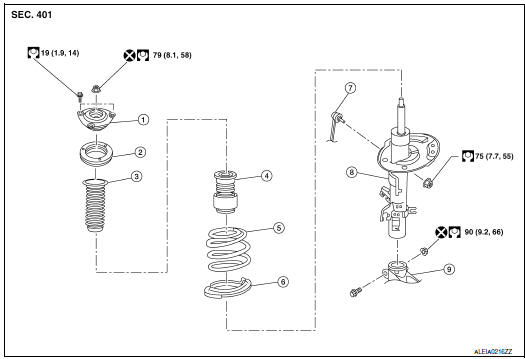
- Strut mount insulator
- Rotary Stop
- Front spring upper rubber seat
- Front suspension bound bumper
- Front spring
- Front spring lower rubber seat
- Stabilizer connecting rod
- Strut
- Steering knuckle
Disassembly and Assembly
DISASSEMBLY
CAUTION: Do not damage the piston rod when removing components from the front coil spring and strut.
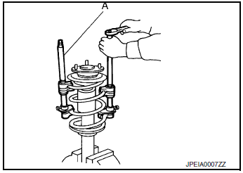
- Install Tool (A) to the front coil spring and strut.
CAUTION: When installing Tool (A), wrap a shop cloth around the front coil spring and strut to protect the parts from damage.
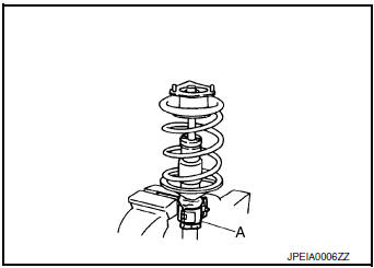
Tool number : ST35652000 ( – )
- Secure Tool (A) in a vise.
- Install a suitable tool to strut rod.
- Slightly loosen the piston rod lock nut.
WARNING: Do not remove the piston rod lock nut completely. If the piston rod lock nut is removed completely, the coil spring can jump out and may cause serious damage or injury.
- Compress the coil spring using a suitable tool (A).
WARNING: Make sure that the pawls of the suitable tool are firmly hooked on the coil spring. The suitable tool must be tightened alternately so as to not tilt the coil spring.
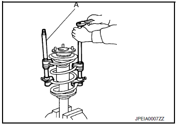
- Make sure coil spring is free between the strut mount insulator and the front spring lower rubber seat.
- Hold the piston rod and remove the piston rod lock nut.
- Remove strut mounting insulator and rotary stop, and front suspension bound bumper from strut.
- Gradually release the suitable tool and remove the coil spring.
CAUTION: Release the suitable tool while making sure the position of the suitable tool on the coil spring does not move.
- Remove front spring lower rubber seat.
- Remove the suitable tool from strut, and inspect the components. Refer to FSU-6, "Inspection".
ASSEMBLY
CAUTION: Do not damage the piston rod when removing components from the front coil spring and strut.
- Install lower rubber seat to the strut.
- Compress the coil spring using a suitable tool.
WARNING: Make sure that the pawls of the suitable tool are firmly hooked on the coil spring. The suitable tool must be tightened alternately so as to not tilt the coil spring.
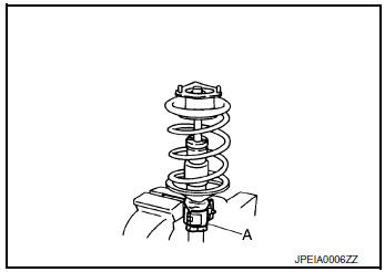
- Align the lower end of the coil spring (1) with the front spring lower rubber seat (2) as shown.
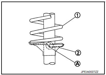
Maximum Gap (A) : 5 mm (0.2 in)
- Connect the bound bumper to the rotary stop and dust boot, then place over strut piston rod.
CAUTION:
- Be sure to install the bound bumper to the rotary stop and dust boot securely.
- When installing the bound bumper, use soapy water. Do not use machine oil of other lubricants.
- Install front spring upper rubber seat to the coil spring.
CAUTION: Do not apply oil, such as grease, when installing the strut mount bearing.
- Temporarily install piston rod lock nut.
CAUTION: Do not reuse piston rod lock nut.
- Gradually release the suitable tool (A) and remove the suitable
tool from coil spring.
CAUTION: Release the suitable tool while making sure the position of the suitable tool on the coil spring does not move.
- Tighten the piston rod lock nut to the specified torque. Refer to FSU-22, "Exploded View".
- Remove Tool (A) from the vise.
- Remove Tool (A) from the front coil spring and strut.
- After replacing strut, always follow the disposal procedure to discard the old strut. Refer to FSU-24, "Disposal".
Inspection
INSPECTION AFTER DISASSEMBLY
Strut
- Check strut for deformation, cracks, and damage, and replace if necessary.
- Check piston rod for damage, uneven wear, and distortion, and replace if necessary.
- Check welded and sealed areas for oil leakage, and replace if necessary.
Insulator and Rubber Parts
Check strut mount insulator for cracks, rubber parts for wear and replace if necessary.
Coil Spring
Check for cracks, wear, and damage and replace if necessary.
Disposal
- Set front coil spring and strut horizontally to the ground with the piston rod fully extracted.
- Drill 2 – 3 mm (0.08 – 0.12 in) hole at the position (
 ) from top
as shown in the figure to release gas gradually.
) from top
as shown in the figure to release gas gradually.
CAUTION:
- Wear eye protection (safety glasses).
- Wear gloves.
- Be careful with metal chips or oil blown out by the compressed gas.
NOTE:
- Drill vertically in this direction (
 ).
). - Directly to the outer tube avoiding brackets.
- The gas is clear, colorless, odorless, and harmless.
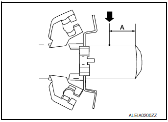
A: 20 – 30 mm (0.79 – 1.18 in)
- Position the drilled hole downward and drain oil by moving the piston rod several times.
CAUTION: Dispose of drained oil according to the law and local regulations.
 Unit removal and installation
FRONT SUSPENSION MEMBER
Exploded View
Front suspension member
Strut mounting bearing
Rebound stopper insulator
Rebound stopper
Removal and Installation
REMOVAL
&nb ...
 Service data and specifications (SDS)
Wheel Alignment (Unladen*1)
*1: Fuel, engine coolant, and lubricants are full. Spare tire, jack, hand
tools, and mats are in designated positions.
Ball Joint
Wheelarch Height (Unladen*)
...
Other materials:
P0117, P0118 ECT sensor
DTC Description
DTC DETECTION LOGIC
DTC No.
CONSULT screen terms
(Trouble diagnosis content)
DTC detecting condition
P0117
ECT SEN/CIRC
(Engine coolant temperature sensor 1 circuit
low)
An excessively low voltage from the engine coolant temperature
sensor i ...
S connector circuit
Description
The starter motor magnetic switch is supplied with power when the ignition
switch is turned to the START position
while the selector lever is in the P (Park) or N (Neutral) position.
Diagnosis Procedure
Regarding Wiring Diagram information, refer to STR-7, "Wiring Diagram" ...
P0705 transmission range sensor A
DTC Description
DTC DETECTION LOGIC
DTC
CONSULT screen terms
(Trouble diagnosis content)
DTC detection condition
P0705
T/M RANGE SENSOR A
[Transmission Range Sensor A Circuit (PRNDL
Input)]
When all of the following conditions are satisfied and this state is
...
