Nissan Rogue Service Manual: P0705 transmission range sensor A
DTC Description
DTC DETECTION LOGIC
| DTC | CONSULT screen terms (Trouble diagnosis content) | DTC detection condition |
| P0705 | T/M RANGE SENSOR A [Transmission Range Sensor A Circuit (PRNDL Input)] | When all of the following conditions are satisfied and this state is
maintained
for 2 seconds:
|
POSSIBLE CAUSE
- Harness or connector (Short circuit between transmission range switch and TCM)
- Transmission range switch
FAIL-SAFE
- Shift position indicator on combination meter is not displayed
- Selector shock is large
- Start is slow
- Acceleration is slow
- Lock-up is not performed
DTC CONFIRMATION PROCEDURE
1.PREPARATION BEFORE WORK
If another "DTC CONFIRMATION PROCEDURE" occurs just before, turn ignition switch OFF and wait for at least 10 seconds, then perform the next test.
>> GO TO 2.
2.CHECK DTC DETECTION
- Turn ignition switch ON.
- Shift the selector lever through entire positions from “P” to “L”. (Hold the selector lever at each position for 5 seconds or more.)
- Check the first trip DTC.
Is “P0705” detected? YES >> Go to TM-107, "Diagnosis Procedure".
NO-1 >> To check malfunction symptom before repair: Refer to GI-41, "Intermittent Incident".
NO-2 >> Confirmation after repair: INSPECTION END
Diagnosis Procedure
1.CHECK TCM INPUT SIGNALS
 With CONSULT
- Turn ignition switch ON.
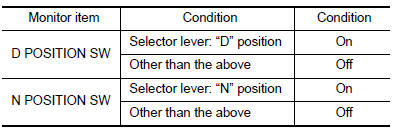
- Select “Data Monitor” in “TRANSMISSION”.
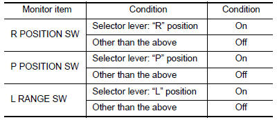
- Select “D POSITION SW”, “N POSITION SW”, “R POSITION SW”, “P POSITION SW” and “L RANGE SW”.
- Shift the selector lever through entire positions from “P” to “L” and check ON/OFF of each monitor item.
 Without CONSULT
- Turn ignition switch OFF.
- Disconnect TCM connector.
- Turn ignition switch ON.
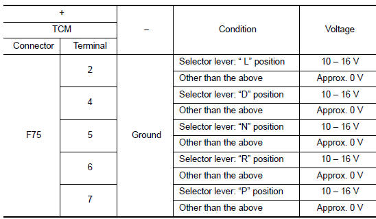
- Shift the selector lever from “P” to “L” and check voltage between TCM harness connector terminals and ground.
Is the inspection result normal? YES >> INSPECTION END
NO-1 [“D POSITION SW” is “ON” when selector is not in “D” position. (Or connector terminal 4 is at power voltage.)]>>GO TO 2.
NO-2 [“N POSITION SW” is “ON” when selector is not in “N” position. (Or connector terminal 5 is at power voltage.)]>>GO TO 4.
NO-3 [“R POSITION SW” is “ON” when selector is not in “R” position. (Or connector terminal 6 is at power voltage.)]>>GO TO 6.
NO-4 [“P POSITION SW” is “ON” when selector is not in “P” position. (Or connector terminal 7 is at power voltage.)]>>GO TO 8.
NO-5 [“L POSITION SW” is “ON” when selector is not in “L” position. (Or connector terminal 2 is at power voltage.)]>>GO TO 10.
2.CHECK D POSITION SW CIRCUIT (PART 1)
- Turn ignition switch OFF.
- Disconnect TCM connector.
- Check continuity between TCM harness connector terminals.
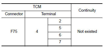
Is the inspection result normal? YES >> GO TO 3.
NO >> Repair or replace malfunctioning parts.
3.CHECK D POSITION SW CIRCUIT (PART 2)
- Disconnect transmission range switch connector.
- Turn ignition switch ON.
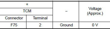
- Check voltage between TCM harness connector terminal and ground.
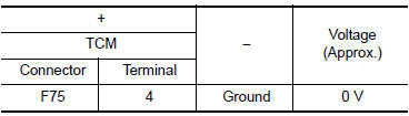
Is the inspection result normal? YES >> GO TO 12.
NO >> Repair or replace malfunctioning parts.
4.CHECK N POSITION SW CIRCUIT (PART 1)
- Turn ignition switch OFF.
- Disconnect TCM connector.
- Check continuity between TCM harness connector terminals.
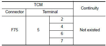
Is the inspection result normal? YES >> GO TO 5.
NO >> Repair or replace malfunctioning parts.
5.CHECK N POSITION SW CIRCUIT (PART 2)
- Disconnect transmission range switch connector.
- Turn ignition switch ON.
- Check voltage between TCM harness connector terminal and ground.
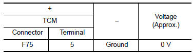
Is the inspection result normal? YES >> GO TO 12.
NO >> Repair or replace malfunctioning parts.
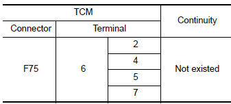
6.CHECK P POSITION SW CIRCUIT (PART 1)
- Turn ignition switch OFF.
- Disconnect TCM connector.
- Check continuity between TCM harness connector terminals.
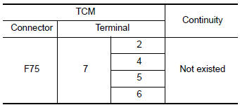
Is the inspection result normal? YES >> GO TO 7.
NO >> Repair or replace malfunctioning parts.
7.CHECK P POSITION SW CIRCUIT (PART 2)
- Disconnect transmission range switch connector.
- Turn ignition switch ON.
- Check voltage between TCM harness connector terminal and ground.
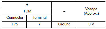
Is the inspection result normal? YES >> GO TO 12.
NO >> Repair or replace malfunctioning parts.
8.CHECK R POSITION SW CIRCUIT (PART1)
- Turn ignition switch OFF.
- Disconnect TCM connector.
- Check continuity between TCM harness connector terminals.
Is the inspection result normal? YES >> GO TO 9.
NO >> Repair or replace malfunctioning parts.
9.CHECK R POSITION SW CIRCUIT (PART 2)
- Disconnect transmission range switch connector.
- Turn ignition switch ON.
- Check voltage between TCM harness connector terminal and ground.
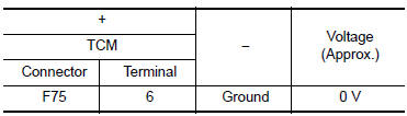
Is the inspection result normal? YES >> GO TO 12.
NO >> Repair or replace malfunctioning parts.
10.CHECK L POSITION SWITCH CIRCUIT (PART 1)
- Turn ignition switch OFF.
- Disconnect TCM connector.
- Check continuity between TCM harness connector terminals.
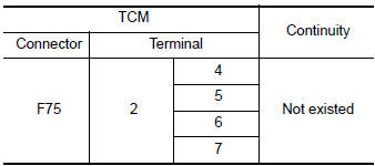
Is the inspection result normal? YES >> GO TO 11.
NO >> Repair or replace malfunctioning parts.
11.CHECK L POSITION SWITCH CIRCUIT (PART 2)
- Disconnect transmission range switch connector.
- Turn ignition switch ON.
- Check voltage between TCM harness connector terminal and ground.
Is the inspection result normal? YES >> GO TO 12.
NO >> Repair or replace malfunctioning parts.
12.CHECK TRANSMISSION RANGE SWITCH
Check transmission range switch. Refer to TM-111, "Component Inspection".
Is the check result normal? YES >> INSPECTION END
NO >> Repair or replace malfunctioning parts.
Component Inspection
1.CHECK TRANSMISSION RANGE SWITCH
Check continuity between transmission range switch connector terminals.
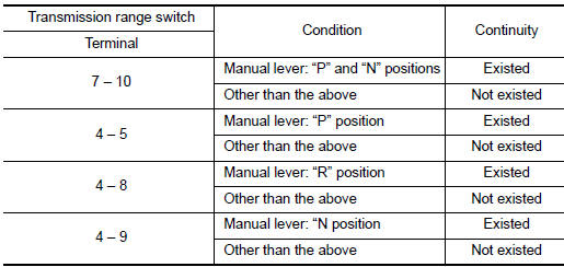
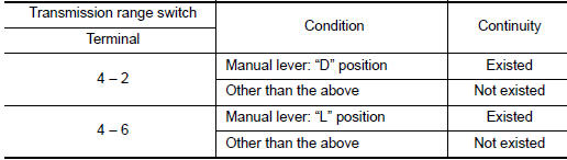
Is the inspection result normal? YES >> INSPECTION END
NO >> There is a malfunction of transmission range switch. Replace transaxle assembly. Refer to TM- 205, "Removal and Installation".
 P062F EEPROM
Description
TCM compares the calculated value stored in the flash ROM with the value
stored in TCM. If the calculated
value does not agree with the stored value, TCM judges this as a malfunction.
...
 P0706 transmission range sensor A
DTC Description
DTC DETECTION LOGIC
DTC
CONSULT screen terms
(Trouble diagnosis content)
DTC detection condition
P0706
T/M RANGE SENSOR A
(Transmission Range Sensor A ...
Other materials:
Brake pedal
Adjustment
BRAKE PEDAL HEIGHT
Remove instrument lower panel LH. Refer to IP-22, "Removal and
Installation".
Disconnect the harness connectors from the stop lamp switch and
brake pedal position switch.
Turn the stop lamp switch and brake pedal position switc ...
Heated seat switch
Exploded View
Center console cup holder
Driver heated seat switch
Passenger heated seat switch
Switch carrier
Pawl
Removal and Installation
REMOVAL
Remove the center console cup holder. Refer to IP-18, "Exploded
View".
Remove screws fro ...
Run-flat tires (if so equipped)
Run-flat tires are those tires that can be used
temporarily if they are punctured. For additional
information, refer to “Run-flat tires” in “Maintenance
and do-it-yourself.”
For additional information, refer to the tire safety
information in the Warranty Information Booklet.
WAR ...
