Nissan Rogue Service Manual: Unit disassembly and assembly
FRONT DRIVE SHAFT
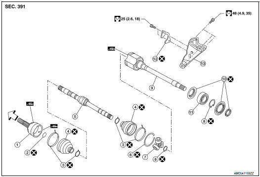
Exploded View (LH)
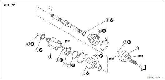
- Shaft
- Circular clip
- Dust shield
- Housing
- Snap ring
- Spider assembly
- Stopper ring
- Boot
- Boot band
- Joint sub-assembly
 Wheel side
Disassembly and Assembly (LH)
DISASSEMBLY
Transaxle Assembly Side
- Fix shaft with a vise.
CAUTION: Protect shaft using aluminum or copper plates when fixing with a vise.
- Remove boot bands, and then remove boot from housing.
- Remove stopper ring.
- Put matching marks on housing and shaft, and then pull out housing
from shaft.
CAUTION: Use paint or an equivalent for matching marks. Do not scratch the surfaces.
- Put matching marks (A) on the spider assembly and shaft.
CAUTION: Use paint or an equivalent for matching marks. Do not scratch the surfaces.
- Remove snap ring (1), and then remove spider assembly from shaft.
- Remove boot from shaft.
- Remove circular clip from housing (left side).
- Remove dust shield from housing.
- Clean old grease on housing with paper waste.
Wheel Side
- Fix shaft with a vise.
CAUTION: Protect shaft using aluminum or copper plates when fixing with a vise.
- Remove boot bands, and then remove boot from joint sub-assembly.
- Screw the drive shaft puller (A) 30 mm (1.18 in) or more into the thread of joint sub-assembly, and pull joint sub-assembly with a sliding hammer (B) from shaft.
CAUTION:
- If joint sub-assembly cannot be removed after five or more unsuccessful attempts, replace shaft and joint sub assembly as a set.
- Align sliding hammer and drive shaft and remove them by pulling forcibly
- Remove circular clip from shaft.
- Remove boot from shaft.
- Clean old grease on joint sub-assembly with paper waste while rotating ball cage.
ASSEMBLY
Transaxle Assembly Side
- Install new boot and boot bands to shaft.
CAUTION:
- Wrap serration on shaft with tape (A) to protect from damage
- Do not reuse boot and boot band.
- Remove the tape wrapped around the serration on shaft.
- To install the spider assembly (1), align it with the matching marks (A) on the shaft (2) put during the removal, and direct the serration mounting surface (B) to the shaft.
- Secure spider assembly onto shaft with snap ring (1).
CAUTION: Do not reuse snap ring.
- Apply the appropriate amount of grease to spider assembly and sliding surface.
- Assemble the housing onto spider assembly, and apply the specified amount of grease.
Grease amount : Refer to FAX-65, "Drive Shaft".
- Align matching marks put during the removal of housing.
- Install stopper ring.
CAUTION: Do not reuse stopper ring.
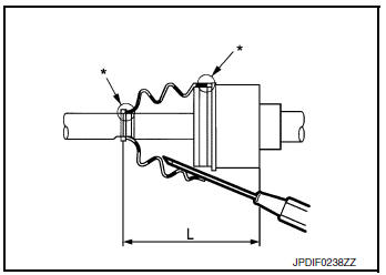
- Install boot securely into grooves (indicated by “*” marks)
shown.
CAUTION: If grease adheres to the boot mounting surface (indicated “*” mark) on shaft or housing, boot may be removed.
Remove all grease from the boot mounting surface.
- To prevent the deformation of the boot, adjust the boot installation length (L) to the value shown below by inserting the suitable tool into the inside of boot from the large diameter side of boot and discharging inside air.
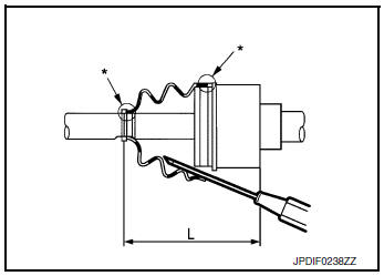
Boots installed length (L) : Refer to FAX-65, "Drive Shaft".
CAUTION:
- If the boot installation length is outside the standard, it may cause breakage of boot.
- Be careful not to touch the inside of the boot with the tip of tool.
- Install new boot bands securely as shown.
CAUTION: Do not reuse boot band.
- Secure housing and shaft, and then make sure that they are in the correct position when rotating boot. Reinstall them with new boot bands when the mounting positions become incorrect.
- Install dust shield to housing (left side).
CAUTION: Do not reuse dust shield.
- Install circular clip to housing (left side).
CAUTION: Do not reuse circular clip.
Wheel Side
For further details, refer to the installation procedure of “FAX-44, "WHEEL SIDE : Removal and Installation"” for the drive shaft boot.
Exploded View (RH)
- Joint sub-assembly
- Circular clip
- Boot band
- Boot
- Shaft
- Damper band
- Dynamic damper
- Stopper ring
- Spider assembly
- Snap ring
- Housing
- Dust shield
- Support bearing
- Retainer
- Support bearing bracket
 : Wheel side
Disassembly and Assembly (RH)
DISASSEMBLY
Transaxle Assembly Side
- Fix shaft with a vise.
CAUTION: Protect shaft using aluminum or copper plates when fixing with a vise.
- Remove boot bands, and then remove boot from housing.
- Remove stopper ring.
- Put matching marks on housing and shaft, and then pull out housing from
shaft.
CAUTION: Use paint or an equivalent for matching marks. Do not scratch the surfaces.
- Put matching marks (A) on the spider assembly and shaft.
CAUTION: Use paint or an equivalent for matching marks. Do not scratch the surfaces.
- Remove snap ring (1), and then remove spider assembly from shaft.
- Remove boot from shaft.
- Remove circular clip from housing (left side).
- Remove dust shield from housing.
- Clean old grease on housing with paper waste.
Support Bearing
- Remove dust shield from housing.
- Remove snap ring (1).
- Press out support bearing from housing.
- Remove dust shield.
Wheel Side
- Fix shaft with a vise.
CAUTION: Protect shaft using aluminum or copper plates when fixing with a vise.
- Remove boot bands, and then remove boot from joint sub-assembly.
- Screw the drive shaft puller (A) 30 mm (1.18 in) or more into the thread of joint sub-assembly, and pull joint sub-assembly with a sliding hammer (B) from shaft.
CAUTION:
- If joint sub-assembly cannot be removed after five or more unsuccessful attempts, replace shaft and joint sub assembly as a set.
- Align sliding hammer and drive shaft and remove them by pulling forcibly.
- Remove circular clip from shaft.
- Remove boot from shaft.
- Clean old grease on joint sub-assembly with paper waste while rotating ball cage.
ASSEMBLY
Transaxle Assembly Side
- Wrap serration on shaft with tape (A) to protect boot from damage.
Install new boot and boot bands to shaft.
CAUTION: Do not reuse boot and boot band.
- Remove the tape wrapped around the serration on shaft.

- To install the spider assembly (1), align it with the matching marks (A) on the shaft (2) put during the removal, and direct the serration mounting surface (B) to the shaft.
- Secure spider assembly onto shaft with snap ring (1).
CAUTION: Do not reuse snap ring.
- Apply the appropriate amount of grease to spider assembly and sliding surface.
- Assemble the housing onto spider assembly, and apply the specified amount of grease.
Grease amount : Refer to FAX-65, "Drive Shaft".
- Align matching marks put during the removal of housing.
- Install stopper ring.
CAUTION: Do not reuse stopper ring.
- Install boot securely into grooves (indicated by “*” marks) shown
in the figure.
CAUTION: If grease adheres to the boot mounting surface (indicated “*” mark) on shaft or housing, boot may be removed.
Remove all grease from the boot mounting surface.
- To prevent the deformation of the boot, adjust the boot installation length (L) to the value shown below by inserting the suitable tool into the inside of boot from the large diameter side of boot and discharging inside air.
Boots installed length (L) : Refer to FAX-65, "Drive Shaft".
CAUTION:
- If the boot installation length is outside the standard, it may cause breakage of boot.
- Be careful not to touch the inside of the boot with the tip of tool.
- Install new boot bands securely as shown in the figure.
CAUTION: Do not reuse boot band.
- Secure housing and shaft, and then make sure that they are in the correct position when rotating boot. Reinstall them with new boot bands when the mounting positions become incorrect.
- Install dust shield to housing (left side).
CAUTION: Do not reuse dust shield.
- Install circular clip to housing (left side).
CAUTION: Do not reuse circular clip.
Support Bearing
- Install dust shield on housing.
CAUTION: Do not reuse dust shield.
- Press support bearing (1) onto housing to using the suitable tool (A).
- Install snap ring.
CAUTION: Do not reuse snap ring.
- Install dust shields.
CAUTION: Do not reuse dust shields.
Wheel Side
For further details, refer to the installation procedure of “FAX-44, "WHEEL SIDE : Removal and Installation"” for the drive shaft boot.
 Removal and installation
FRONT WHEEL HUB
Exploded View
Wheel hub and bearing
Cotter pin
Nut retainer
Wheel hub lock nut
Hub bolt
Splash guard
Steering knuckle
Removal and In ...
 Service data and specifications (SDS)
Wheel Bearing
Drive Shaft
Drive Shaft Specifications
*Always check with the Parts Department for the latest parts information.
Dynamic Damper Specifications
Boot Band Specification
...
Other materials:
Heating and cooling unit assembly
Exploded View
Steering Member
Heating and cooling unit assembly
Steering member
Bolt
Nut
Automatic Air Conditioning
Wiring harness
Air mix door duct (LH)
Air mix door duct (RH)
Intake housing gasket
Blower motor
Front foot duct (RH)
...
On board diagnostic (OBD) system
Diagnosis Description
This system is an on board diagnostic system that records exhaust
emission-related diagnostic information
and detects a sensors/actuator-related malfunction. A malfunction is indicated
by the malfunction indicator
lamp (MIL) and stored in ECU memory as a DTC. The diagnos ...
Rear door finisher
Exploded View
Rear door
Rear power window switch finisher
Rear door screw cover
Rear door inside handle finisher
Rear door finisher
Tether clip
Tether
Pawl
Clip
Removal and Installation
REMOVAL
Remove screw cover (1).
Remo ...
