Nissan Rogue Service Manual: Heating and cooling unit assembly
Exploded View
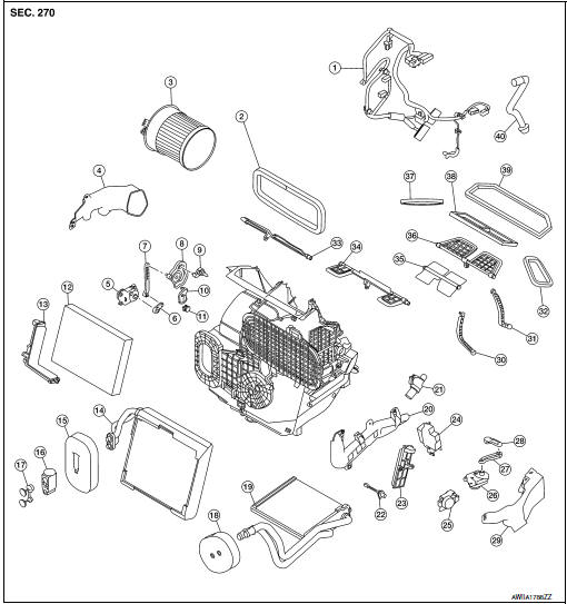
Steering Member
- Heating and cooling unit assembly
- Steering member
- Bolt
- Nut
Automatic Air Conditioning
- Wiring harness
- Air mix door duct (LH)
- Air mix door duct (RH)
- Intake housing gasket
- Blower motor
- Front foot duct (RH)
- Mode door motor
- Mode door motor link
- Mode door motor link 2
- Mode door motor main link
- Rear foot door lever
- Front foot door link
- Front foot door lever
- Air mix door motor (RH)
- Air mix door motor link (RH)
- Air mix door motor link 2 (RH)
- Air mix door lever (RH)
- In-cabin microfilter
- In-cabin microfilter cover
- Evaporator
- Evaporator grommet
- Expansion valve
- Expansion valve plug
- Heater core
- Heater core grommet
- Heater core pipe cover
- Aspirator
- Intake sensor
- Inspection cover
- Variable blower control
- Air mix door motor (LH)
- Front foot duct (LH)
- Intake door motor
- Intake door motor link
- Intake door lever
- Internal door linkage 1
- Internal door linkage 2
- Side ventilator duct gasket (LH)
- Rear foot door
- Front foot door
- Center ventilator door
- Defroster door
- Side ventilator duct gasket (RH)
- Center ventilator duct gasket
- Defroster duct gasket
- Drain hose
Manual Air Conditioning
- Wiring harness
- Intake housing gasket
- Blower motor
- Front foot duct
- Mode door motor
- Mode door motor link
- Mode door motor link 2
- Mode door motor main link
- Rear foot door lever
- Front foot door link
- Front foot door lever
- In-cabin microfilter
- In-cabin microfilter cover
- Evaporator
- Evaporator grommet
- Expansion valve
- Expansion valve plug
- Heater core grommet
- Heater core
- Heater core pipe cover
- Aspirator
- Intake sensor
- Inspection cover
- Variable blower control
- Air mix door motor
- Intake door motor
- Intake door motor link
- Intake door lever
- Front foot duct (LH)
- Internal door linkage 1
- Internal door linkage 2
- Side ventilator duct gasket (LH)
- Rear foot door
- Front foot door
- Center ventilator door
- Defroster door
- Side ventilator duct gasket (RH)
- Center ventilator duct gasket
- Defroster duct gasket
- Drain hose
HEATING AND COOLING UNIT ASSEMBLY
HEATING AND COOLING UNIT ASSEMBLY : Removal and Installation
REMOVAL
CAUTION: Before servicing, turn the ignition switch off, disconnect both battery cables and wait at least three minutes.
NOTE: When removing components such as hoses, lines/tubes, etc., cap or plug openings to prevent fluid from leaking.
- Disconnect the negative and positive battery terminals and wait at least three minutes. Refer to PG-75, "Removal and Installation (Battery)".
- Discharge the refrigerant. Refer to HA-23, "Recycle Refrigerant".
- Drain the engine coolant. Refer to CO-8, "Draining".
- Remove instrument panel assembly. Refer to IP-14, "INSTRUMENT PANEL ASSEMBLY : Removal and Installation".
- Remove steering column. Refer to ST-12, "Removal and Installation".
- Remove dash side finishers (LH/RH). Refer to INT-24, "DASH SIDE FINISHER : Removal and Installation".
- Remove front floor connecting ducts (LH/RH). Refer to VTL-10, "FRONT FLOOR DUCT : Removal and Installation - Front Floor Connecting Duct".
- Remove the cowl top extension. Refer to EXT-25, "Removal and Installation".
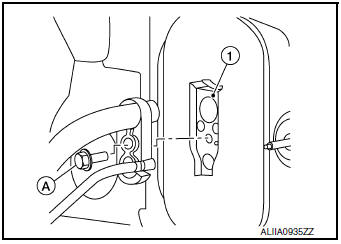
- Remove the bolt (A) that retains the low-pressure pipe and highpressure pipe to the expansion valve (1).
CAUTION: Cap or wrap the joint of the pipe with suitable material such as vinyl tape to avoid the entry of air.
- Disconnect the heater hoses from the heater core.
- Remove the nuts and bolts that retain the steering member to the vehicle body.
- Disconnect the drain hose from the heating and cooling unit assembly.
- Disconnect the harness connectors from the heating and cooling unit assembly and steering member.
- Remove the heating and cooling unit assembly and steering member
from the vehicle as an assembly.
CAUTION: Use care not to damage the seats when removing the steering member.
- Remove the bolts that retain the heating and cooling unit assembly to the steering member.
- Separate the heating and cooling unit assembly from the steering member.
INSTALLATION
Installation is in the reverse order of removal.
CAUTION:
- Do not reuse O-rings.
- Apply A/C oil to new O-rings for installation.
- After charging refrigerant, check for leaks. Refer to HA-21, "Leak Test".
HEATER CORE
HEATER CORE : Exploded View
- Heating and cooling unit assembly
- Heater core
- Heater core grommet
- Heater core pipe cover
 Front
Front
HEATER CORE : Removal and Installation
REMOVAL
NOTE: When removing components such as hoses, lines/tubes, etc., cap or plug openings to prevent fluid from spilling.
- Discharge the refrigerant. Refer to HA-23, "Recycle Refrigerant".
- Drain the engine coolant. Refer to CO-8, "Draining".
- Remove heating and cooling unit assembly. Refer to HA-42, "HEATING AND COOLING UNIT ASSEMBLY : Removal and Installation".
- Remove front foot duct (LH). Refer to VTL-10, "FRONT FOOT DUCT : Removal and Installation".
- Remove screws and heater core pipe cover. Refer to HA-39, "Exploded View".
- Remove heater core.
INSTALLATION
Installation is in the reverse order of removal.
EVAPORATOR
EVAPORATOR : Exploded View
- Evaporator
- Expansion valve
- Heating and cooling unit assembly
EVAPORATOR : Removal and Installation
REMOVAL
- Discharge the refrigerant. Refer to HA-23, "Recycle Refrigerant".
- Remove front foot duct (LH). Refer to VTL-10, "FRONT FOOT DUCT : Removal and Installation".
- Remove heater core. Refer to HA-43, "HEATER CORE : Removal and Installation".
- Remove intake door motor. Refer to HAC-110, "INTAKE DOOR MOTOR : Removal and Installation" (AUTOMATIC AIR CONDITIONING) or HAC-185, "INTAKE DOOR MOTOR : Removal and Installation" (MANUAL AIR CONDITIONING).
- Remove air mix door motor (LH) (AUTOMATIC AIR CONDITONING). Refer to HAC-110, "AIR MIX DOOR MOTOR : Removal and Installation".
- Remove air mix door motor (MANUAL AIR CONDITIONING). Refer to HAC-185, "AIR MIX DOOR MOTOR : Removal and Installation".
- Separate the heating and cooling unit assembly and remove evaporator.
INSTALLATION
Installation is in the reverse order of removal.
CAUTION:
- Do not reuse O-rings.
- Apply A/C oil to new O-rings for installation.
- After charging the refrigerant, check for leaks. Refer to HA-21, "Leak Test"
EXPANSION VALVE
EXPANSION VALVE : Removal and Installation
REMOVAL
- Discharge the refrigerant. Refer to HA-23, "Recycle Refrigerant".
- Remove cowl top extension. Refer to EXT-25, "Removal and Installation".
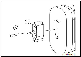
- Remove the bolt (A) that retains the low-pressure pipe and highpressure
pipe to the expansion valve (1).
CAUTION: Cap or wrap the joint of the pipe with suitable material such as vinyl tape to avoid the entry of air.
- Remove bolts (A) and expansion valve (1).
INSTALLATION
Installation is in the reverse order of removal.
CAUTION:
- Tighten bolts to specification. Refer to HA-32, "Exploded View".
- Do not reuse O-rings.
- Apply A/C oil to new O-rings for installation.
- After charging refrigerant, check for leaks. Refer to HA-21, "Leak Test".
 Condenser
Exploded View
Air guide (LH)
Condenser upper bracket (LH)
Condenser (includes liquid tank)
Condenser upper bracket (RH)
Air guide (RH)
Refrigerant pressure sensor
C ...
 Service data and specifications (SDS)
Compressor
Oil
Refrigerant
...
Other materials:
Sun visors
Sun visors
To block glare from the front, swing down the
main sun visor.
To block glare from the side, remove the
main sun visor from the center mount and
swing the visor to the side.
To extend the sun visor, slide in or out as
needed.
CAUTION
Do not ...
CAN system (type 8)
MAIN LINE BETWEEN IPDM-E AND DLC CIRCUIT
Diagnosis Procedure
1.CHECK CONNECTOR
Turn the ignition switch OFF.
Disconnect the battery cable from the negative terminal.
Check the following terminals and connectors for damage, bend and
loose connection (connector side
an ...
Power panoramic moonroof (if so equipped)
The moonroof will only operate when the ignition
switch is placed in the ON position. The moonroof
is operational for a period of time, even if the
ignition switch is placed in the ACC (if so
equipped) or OFF position. If the driverŌĆÖs door or
the front passengerŌĆÖs door is opened during ...
