Nissan Rogue Service Manual: Rear door finisher
Exploded View
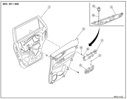
- Rear door
- Rear power window switch finisher
- Rear door screw cover
- Rear door inside handle finisher
- Rear door finisher
- Tether clip
- Tether
 Pawl
Pawl
 Clip
Clip
Removal and Installation
REMOVAL
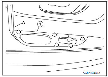
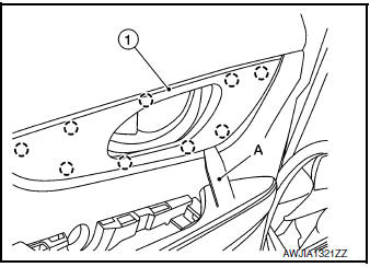
- Remove screw cover (1).
- Remove screw (A).
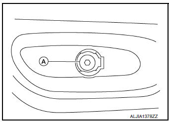
- Release pawls using a suitable tool (A) and remove rear power window switch finisher (1).
 : Pawl
- Disconnect harness connector from rear power window switch finisher.
- Release pawls using a suitable tool (A) and remove rear door inside handle finisher (1).
 : Pawl
- Release clip and remove tether from the front door panel.
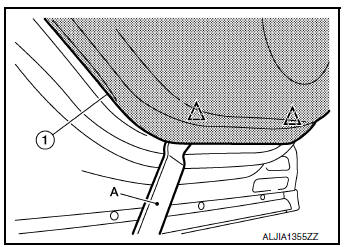
- Release clips using a suitable tool (A) and remove rear door finisher (1).
 : Clip
INSTALLATION
Installation is in the reverse order of removal.
CAUTION:
- Visually check the clips and pawls for deformation and damage during installation. Replace with new ones if necessary.
- When installing rear door finisher, check that clips and pawls are securely placed in door panel holes.
 Front door finisher
Exploded View
Front door
Front door pull handle bracket
Front door pull handle
Front power window switch (RH)
finisher
Front door inside handle finisher
Front door finisher
C ...
 Body side trim
Exploded View
Front pillar finisher
Front body side welt
Center pillar upper finisher
Rear body side welt
Rear kicking plate
Seat belt cover
Center pillar lower fin ...
Other materials:
Removal and installation
EXHAUST SYSTEM
Exploded View
Exhaust diffuser
Muffler assembly
Mounting rubber
Mounting rubber
Mounting rubber
Ring gasket
Front exhaust tube
Mounting rubber
Exhaust gasket
Oxygen sensor 2
Center exhaust tube
Catalyst shroud
...
C1198 vacuum sensor
DTC Logic
DTC DETECTION LOGIC
DTC
Display Item
Malfunction detected condition
Possible causes
C1198
VACUUM SEN CIR
When an open circuit is detected in vacuum sensor
circuit.
When a short circuit is detected in vacuum sensor
circuit.
&nb ...
Operation
Switch Name and Function
STEERING SWITCH
No.
Switch name
Operation
Description
1
Enter/Up/Down switch
Press
The information display settings can be changed.
2
Display switch
3
Back switch
METER CONTROL SWITCH
No.
Sw ...
