Nissan Rogue Service Manual: Removal and installation
FRONT WHEEL HUB
Exploded View
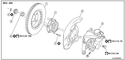
- Wheel hub and bearing
- Cotter pin
- Nut retainer
- Wheel hub lock nut
- Hub bolt
- Splash guard
- Steering knuckle
Removal and Installation
REMOVAL
- Remove front wheel and tire using power tool. Refer to WT-57, "Adjustment".
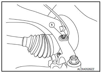
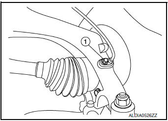
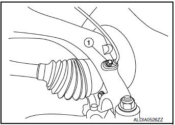
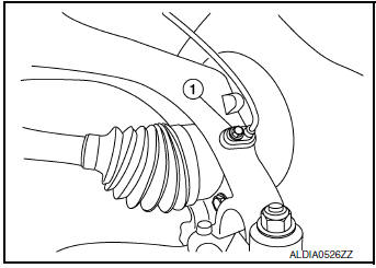
- Remove the bolt (1) and separate the front wheel sensor from the steering knuckle. Refer to BRC-132, "FRONT WHEEL SENSOR : Exploded View".
CAUTION:
- Failure to separate the front wheel sensor from the steering knuckle may result in damage to the front wheel sensor.
- Pull out the front wheel sensor, being careful to turn it as little as possible. Do not pull on wheel sensor harness.
- Remove brake caliper torque member bolts, leaving brake hose attached,
reposition the caliper aside with
wire. Refer to BR-35, "BRAKE CALIPER ASSEMBLY (1 PISTON TYPE) : Exploded
View" (1 PISTON
TYPE), or BR-35, "BRAKE CALIPER ASSEMBLY (1 PISTON TYPE) : Exploded View" (2
PISTON TYPE).
CAUTION: Do not depress brake pedal while brake caliper is removed.
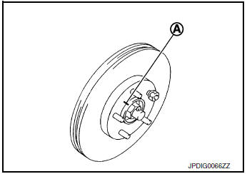
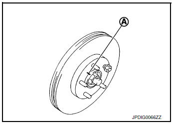
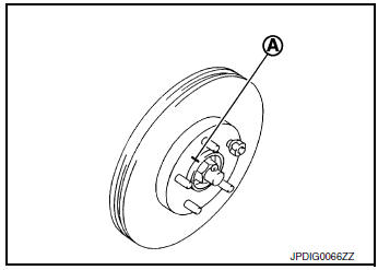
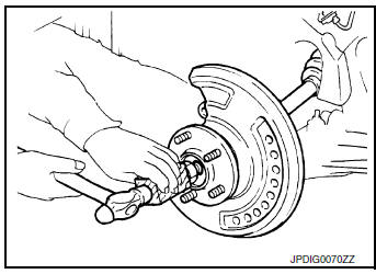
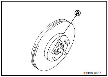
- Put alignment marks (A) on disc brake rotor and wheel hub and
bearing. Remove disc brake rotor.
CAUTION: Do not drop the disc brake rotor.

- Remove cotter pin.
- Remove the nut retainer.
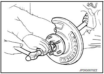
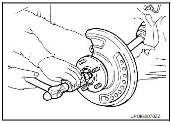
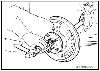
- Loosen the wheel hub lock nut from the drive shaft using power tool.
- Using a piece of wood and a suitable tool, tap on the lock nut to disengage the drive shaft from the wheel hub and bearing.
CAUTION:
- Do not place the drive shaft joint at an extreme angle. Be careful not to over extend the slide joint.
- Do not allow the drive shaft to hang without support.
NOTE: Use a suitable puller if drive shaft cannot be separated from the wheel hub and bearing.
- Remove the wheel hub lock nut.
- Remove the engine side cover. Refer to EXT-28, "FENDER PROTECTOR : Exploded View".
- Remove the lower nut and bolt from the steering knuckle. Refer to FAX-9, "Exploded View".
- Separate transverse link from steering knuckle. Refer to FSU-12, "Exploded View".
- Separate drive shaft from wheel hub and bearing, Reposition the drive shaft aside with wire. Refer to FAX- 18, "Exploded View (LH)" (LH) or FAX-20, "Exploded View (RH)" (RH).
- Remove the wheel hub and bearing bolts using power tool.
- Remove the splash guard and the wheel hub and bearing from the steering knuckle.
INSPECTION AFTER REMOVAL
Check the following items, and replace the part if necessary.
- Check components for deformation, cracks, and other damage.
- Check boots of transverse link ball joint for cracks, axial end play, and swing torque. Refer to FAX-65, "Drive Shaft".
INSTALLATION
Installation is in the reverse order of the removal.
CAUTION:
- Do not reuse the wheel stud.
- Do not reuse the cotter pin.
- Place a washer (A) as shown to install the wheel studs (1) by using the tightening force of the nut (B).
CAUTION: Check that there is no clearance between the wheel stud and the wheel hub and bearing.
- Clean the mating surfaces of the wheel hub lock nut and the wheel hub
and bearing.
CAUTION: Do not apply lubricating oil to these mating surfaces.
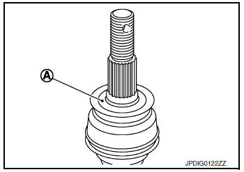
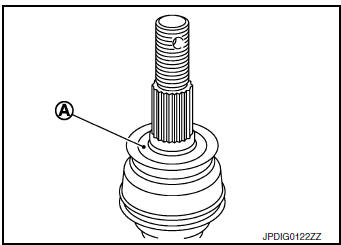
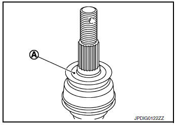
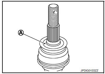
- Clean the mating surfaces of the joint sub-assembly and the wheel
hub and bearing. Apply Molykote M77 lubricant to the surface (A)
of the joint sub-assembly.
CAUTION: Apply lubricant to cover the entire flat mating surface of the joint sub-assembly.
Amount of lubricant : FAX-65, "Drive Shaft"
NOTE: Always check with the Parts Department for the latest parts information.
- Hold the wheel hub and bearing using a suitable tool. Tighten the wheel hub lock nut.
CAUTION:
- Since the drive shaft is assembled by press-fitting, use a torque wrench to tighten the wheel hub lock nut. Do not use a power tool.
- Too much torque causes axle noise. Too little torque causes wheel bearing looseness. Tighten the wheel hub lock nut to the specification.
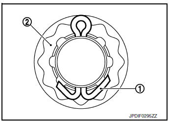
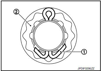
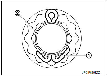
- When installing a the cotter pin (1) and the nut retainer (2), securely bend the cotter pin to prevent rattles.
- Align the matching marks (A) on the disc brake rotor and on the wheel hub and bearing.
- Complete the inspection. Refer to FAX-42, "Inspection".
INSPECTION AFTER INSTALLATION
- Check the wheel alignment. Refer to FSU-7, "Inspection".
- Adjust neutral position of steering angle sensor. Refer to BRC-70, "Work Procedure".
Inspection
INSPECTION AFTER REMOVAL
Check components for deformation, cracks, and other damage. Replace if there are.
Ball Joint Inspection
Check boots of transverse link and steering outer socket ball joint for breakage, axial play, and torque. Refer to FSU-26, "Ball Joint" and ST-15, "Inspection".
INSPECTION AFTER INSTALLATION
- Check the wheel alignment. Refer to FSU-7, "Inspection".
- Adjust neutral position of steering angle sensor. Refer to BRC-70, "Work Procedure".
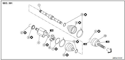
FRONT DRIVE SHAFT BOOT
Exploded View
LH
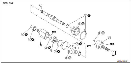
- Shaft
- Circular clip
- Dust shield
- Housing
- Snap ring
- Spider assembly
- Stopper ring
- Boot
- Boot band
- Joint sub-assembly
 : Wheel side
RH
- Shaft
- Circular clip
- Dust shield
- Housing
- Snap ring
- Spider assembly
- Stopper ring
- Boot
- Boot band
- Joint sub-assembly
: Wheel side
WHEEL SIDE
WHEEL SIDE : Removal and Installation
REMOVAL
- Remove front wheel and tire using power tool. Refer to WT-57, "Adjustment".
- Remove the bolt (1) and separate the front wheel sensor from the steering knuckle. Refer to BRC-132, "FRONT WHEEL SENSOR : Removal and Installation".
CAUTION:
- Failure to separate the front wheel sensor from the steering knuckle may result in damage to the front wheel sensor.
- Pull out the front wheel sensor, being careful to turn it as little as possible. Do not pull on front wheel sensor harness
- Remove brake caliper torque member bolts, leaving brake hose attached,
reposition the caliper aside with
wire. Refer to BR-35, "BRAKE CALIPER ASSEMBLY (1 PISTON TYPE) : Exploded
View" (1 PISTON
TYPE), or BR-35, "BRAKE CALIPER ASSEMBLY (1 PISTON TYPE) : Exploded View" (2
PISTON TYPE).
CAUTION: Do not depress brake pedal while brake caliper is removed.
- Put alignment marks (A) on disc brake rotor and wheel hub and
bearing. Remove disc brake rotor.
CAUTION: Do not drop the disc brake rotor.
- Remove cotter pin.
- Remove the nut retainer.
- Loosen the wheel hub lock nut from the drive shaft using power tool.
- Using a piece of wood and a suitable tool, tap on the lock nut to disengage the drive shaft from the wheel hub and bearing.
CAUTION:
- Do not place the drive shaft joint at an extreme angle. Be careful not to over extend the slide joint.
- Do not allow the drive shaft to hang without support.
NOTE: Use a suitable puller if drive shaft cannot be separated from the wheel hub and bearing.
- Remove the wheel hub lock nut.
- Remove the engine side cover. Refer to EXT-28, "FENDER PROTECTOR : Exploded View".
- Remove the lower nut and bolt from the steering knuckle (shown in explode). Separate the transverse link from the steering knuckle. Refer to FAX-9, "Exploded View".
- Separate drive shaft from wheel hub and bearing, Reposition the drive shaft aside with wire. Refer to FAX- 40, "Exploded View".
- Remove boot bands.
- Remove boot from joint sub-assembly.
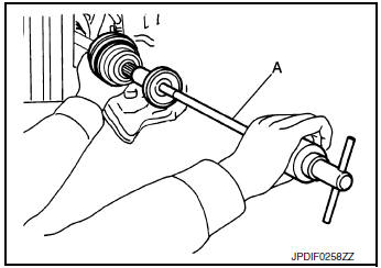
- Screw a suitable tool (A) 30 mm (1.18 in) or more into threaded part of joint sub-assembly. Support drive shaft with one hand and pull out joint sub-assembly with a sliding hammer or suitable tool from housing assembly.
CAUTION:
- Align sliding hammer or suitable tool and drive shaft and remove joint sub-assembly by pulling directly.
- If joint sub-assembly cannot be removed after five or more unsuccessful attempts, replace the entire drive shaft assembly.
- Remove circular clip (1) from shaft.
- Remove outer boot from shaft.
- Inspect the components. Refer to FAX-48, "Inspection".
INSTALLATION
- Clean the old grease on joint sub-assembly with paper shop cloth.
- Fill serration slot joint sub-assembly with NISSAN genuine grease
or equivalent.
CAUTION: After applying grease, use a paper shop cloth to wipe off old grease that has oozed out.
NOTE: Always check with the Parts Department for the latest parts information.
- Install boot and boot bands to shaft.
CAUTION:
- Wrap serration on shaft with tape to protect the boot from damage.
- Do not reuse boot and boot band.
- Remove the tape wrapped around the serration on shaft.
- Position the circular clip (1) on groove at the shaft edge.
CAUTION: Do not reuse circular clip.
NOTE: A drive joint inserter is recommended when installing the circular clip.
- Align of the shaft and joint sub-assembly. Assemble the shaft with joint sub-assembly while holding the circular clip.
- Install joint sub-assembly (1) to housing assembly using suitable
tool.
CAUTION: Confirm that joint sub-assembly is correctly engaged while rotating drive housing assembly.
- Apply the specified amount of grease into the large diameter side opening of the boot.
Grease amount : Refer to FAX-65, "Drive Shaft".
- Install the boot securely into grooves (indicated by “*” marks)
shown in the figure.
CAUTION: If grease adheres to the boot mounting surface (indicated by “*” mark) on the shaft or the joint sub-assembly, boot may come off. Remove all grease from the boot mounting surface.
- Make sure boot installation length (L) is the specified length.
Insert a suitable tool into the large end of boot. Bleed air from boot to prevent boot deformation.
Boot installation length (L) : Refer to FAX-65, "Drive Shaft".
CAUTION:
- Boot may break if boot installation length is not within standard value.
- Be careful that suitable tool does not contact inside surface of boot.
- Install new large and small boot bands securely using Tool.
Tool number : KV40107300 ( — )
CAUTION: Do not reuse boot band.
- Secure boot band so that dimension (M) meets the specification as shown
Dimension (M) : Refer to FAX-65, "Drive Shaft".
- Attempt to rotate the boot to check whether or not the boot bands are securing the boot. If the boot is not secure, remove the boot bands, reposition the boot, and install new boot bands.
- Clean the mating surfaces of the joint sub-assembly and the
wheel hub and bearing. Apply Molykote M77 lubricant to the surface
(A) of the joint sub-assembly.
CAUTION: Apply lubricant to cover the entire flat mating surface of the joint sub-assembly.
Amount of lubricant FAX-65, "Drive Shaft"
NOTE: Always check with the Parts Department for the latest parts information.
- Clean the mating surface of the drive shaft (A) and the wheel hub and bearing.
- Insert drive shaft to wheel hub and bearing.
- Temporarily install the wheel hub lock nut.
CAUTION: Do not reuse the wheel hub lock nut.
- Install the transverse link to the steering knuckle. Tighten the
steering knuckle nut and bolt to the specification.
Refer to FSU-12, "Exploded View".
- Align the marks on the disc brake rotor and on the wheel hub and bearing. Install the disc brake rotor.
- Install caliper to steering knuckle. Refer to FSU-17, "Exploded View".
- Install the front wheel sensor to the steering knuckle. Refer to BRC-132, "FRONT WHEEL SENSOR : Exploded View".
CAUTION:
- Before installling, make sure there is no foreign material such as iron fragments adhered to the pick-up part of the front wheel sensor.
- When installing, make sure there is no foreign material such as iron fragments on and in the hole in the steering knuckle for the front wheel sensor. Make sure no foreign material has been caught in the sensor rotor. Remove any foreign material and then install the front wheel sensor.
- Hold the wheel hub and bearing. tighten the wheel hub lock nut. Refer to FAX-40, "Exploded View".
CAUTION:
- Since the drive shaft is assembled by press-fitting, use a torque wrench to tighten the wheel hub lock nut. Do not use a power tool.
- Too much torque causes axle noise. too little torque causes wheel bearing loosness. Tighten the wheel hub lock nut to the specification.
- Install the nut retainer.
- Install a new cotter pin. Refer to FAX-40, "Exploded View".
CAUTION:
- Do not reuse cotter pin.
- Bend cotter pin securely to prevent any looseness.
- Install the front wheel and tire. Refer to WT-60, "Removal and Installation".
TRANSAXLE SIDE
TRANSAXLE SIDE : Removal and Installation
NOTE: Remove boot after removing drive shaft.
- For drive shaft removal and installation, refer to FAX-18, "Removal and Installation (LH)".
- For drive shaft disassembly and assembly, refer to FAX-57, "Disassembly and Assembly (LH)" (LH) or FAX- 60, "Disassembly and Assembly (RH)" (RH).
Inspection
INSPECTION AFTER INSTALLATION
Check the following items, and replace the part if necessary.
- Move joint up/down, left/right, and in the axial directions. Check for motion that is not smooth and for significant looseness.
- Check boot for cracks, damage, and leakage of grease.
- Check the wheel sensor harness to be sure the connectors are fully seated.
- Check the wheel alignment. Refer to FSU-7, "Inspection".
FRONT DRIVE SHAFT
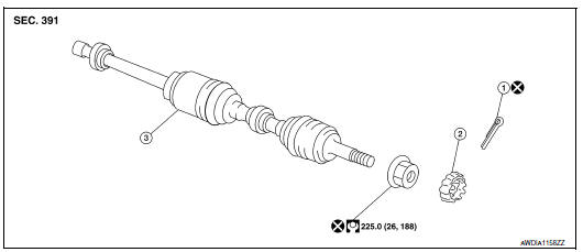
Exploded View (LH)
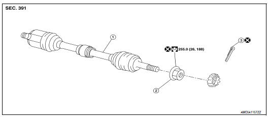
- Drive shaft
- Nut retainer
- Cotter pin
Removal and Installation (LH)
REMOVAL
- Remove front wheel and tire using power tool. Refer to WT-57, "Adjustment".
- Remove the bolt (1) and separate the front wheel sensor from the steering knuckle. Refer to BRC-132, "FRONT WHEEL SENSOR : Exploded View".
CAUTION:
- Failure to separate the front wheel sensor from the steering knuckle may result in damage to the front wheel sensor.
- Pull out the front wheel sensor, being careful to turn it as little as possible. Do not pull on wheel sensor harness.
- Remove brake caliper torque member bolts, leaving brake hose attached,
reposition the caliper aside with
wire. Refer to BR-35, "BRAKE CALIPER ASSEMBLY (1 PISTON TYPE) : Exploded
View" (1 PISTON
TYPE), or BR-35, "BRAKE CALIPER ASSEMBLY (1 PISTON TYPE) : Exploded View" (2
PISTON TYPE).
CAUTION: Do not depress brake pedal while brake caliper is removed.
- Put alignment marks (A) on disc brake rotor and wheel hub and
bearing. Remove disc brake rotor.
CAUTION: Do not drop the disc brake rotor.
- Remove cotter pin.
- Remove the nut retainer.
- Loosen the wheel hub lock nut from the drive shaft using power tool.
- Using a piece of wood and a suitable tool, tap on the lock nut to disengage the drive shaft from the wheel hub and bearing.
CAUTION:
- Do not place the drive shaft joint at an extreme angle. Be careful not to over extend the slide joint.
- Do not allow the drive shaft to hang without support.
NOTE: Use a suitable puller if drive shaft cannot be separated from the wheel hub and bearing.
- Remove the wheel hub lock nut.
- Remove the engine side cover. Refer to EXT-28, "FENDER PROTECTOR : Exploded View".
- Remove the lower nut and bolt from the steering knuckle. Refer to FAX-50, "Exploded View (LH)".
- Separate transverse link from steering knuckle. Refer to FSU-12, "Exploded View".
- Separate drive shaft from wheel hub and bearing, Reposition the drive shaft aside with wire. Refer to FAX- 40, "Exploded View".
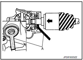
- Remove drive shaft from transaxle assembly.
- Use the Tool (A) and a suitable tool (B) while inserting tip of Tool (A) between housing and transaxle assembly.
CAUTION:
- Do not place drive shaft joint at an extreme angle when removing drive shaft. Also be careful not to overextend slide joint.
- Confirm that the circular clip is attached to the drive shaft.
Tool (A) : KV40107500 ( –– )
INSTALLATION
Installation is in the reverse order of removal.
- Install a new differential side oil seal. Refer to TM-210, "Removal and Installation".
CAUTION: Do not reuse the differential side oil seal.
- Place Tool (A) onto transaxle assembly to prevent damage to the differential side oil seal while inserting drive shaft. Slide drive shaft sliding joint and tap with a suitable tool to install securely.
CAUTION: Check that circular clip is completely engaged.
Tool (A) : KV38107900 ( –– )
- Clean the matching surface of wheel hub lock nut and wheel hub and bearing.
CAUTION: Do not apply lubricating oil to these matching surface.
- Clean the matching surface of drive shaft, wheel hub and bearing.
And then apply Molykote M77 lubricant to surface (A) of joint subassembly of drive shaft.
CAUTION: Apply paste to cover entire flat surface of joint sub-assembly of drive shaft.
Amount of lubricant : 1.0 – 3.0 g (0.04 – 0.10 oz)
CAUTION:
- Since the drive shaft is assembled by press-fitting, use the tightening torque range for the wheel hub lock nut.
- Be sure to use torque wrench to tighten the wheel hub lock nut. Do not use a power tool.
- Do not reuse wheel hub lock nut.
- Too much torque causes axle noise. Too little torque, causes
wheel hub and bearing looseness.
Tighten the wheel hub lock nut to the specification.
- Align the matching marks that have been made during removal when reusing the disc brake rotor.
- When installing a cotter pin (1) and nut retainer (2), securely bend the cotter pin to prevent rattles.
CAUTION: Do not reuse cotter pin.
- Perform the final tightening of each of parts under unladen conditions, which were removed when removing wheel hub and bearing and steering knuckle.
Exploded View (RH)
- Cotter pin
- Nut retainer
- Drive shaft
Removal and Installation (RH)
REMOVAL
- Remove front wheel and tire using power tool. Refer to WT-57, "Adjustment".
- Remove wheel sensor bolt (A) and position wheel sensor aside.
Refer to BRC-132, "FRONT WHEEL SENSOR : Removal and Installation".
CAUTION: Do not pull on wheel sensor harness.
- Remove brake caliper torque member bolts, leaving brake hose attached,
reposition the caliper aside with
wire. Refer to BR-35, "BRAKE CALIPER ASSEMBLY (1 PISTON TYPE) : Exploded
View" (1 PISTON
TYPE), or BR-35, "BRAKE CALIPER ASSEMBLY (1 PISTON TYPE) : Exploded View" (2
PISTON TYPE).
CAUTION: Do not depress brake pedal while brake caliper is removed.
- Put alignment marks (A) on disc brake rotor and wheel hub and
bearing. Remove disc brake rotor.
CAUTION: Do not drop the disc brake rotor.
- Remove cotter pin.
- Remove the nut retainer.
- Loosen the wheel hub lock nut from the drive shaft using power tool.
- Using a piece of wood and a hammer, tap on the lock nut to disengage the drive shaft from the wheel hub and bearing.
CAUTION:
- Do not place the drive shaft joint at an extreme angle. Be careful not to over extend the slide joint.
- Do not allow the drive shaft to hang without support.
NOTE: Use a suitable puller if drive shaft cannot be separated from the wheel hub and bearing.
- Remove the wheel hub lock nut.
- Remove the engine side cover. Refer to EXT-28, "FENDER PROTECTOR : Exploded View".
- Separate transverse link from steering knuckle. Refer to FSU-12, "Exploded View".
- Separate drive shaft from wheel hub and bearing and reposition drive shaft aside with wire.
- Remove retainer mounting bolts and retainer.
- If necessary, remove the support bearing bracket mounting bolts and the support bearing bracket.
- Remove drive shaft from transaxle assembly.
- Use the Tool (A) and a suitable tool (B) while inserting tip of Tool (A) between housing and transaxle assembly.
CAUTION:
- Do not place drive shaft joint at an extreme angle when removing drive shaft. Also be careful not to overextend slide joint.
Tool : KV40107500 ( –– )
INSTALLATION
- Install a new differential side oil seal. Refer to TM-210,
"Removal and Installation".
CAUTION: Do not reuse the differential side oil seal.
- Place Tool (A) onto transaxle assembly to prevent damage to
the differential side oil seal while inserting drive shaft. Slide drive
shaft sliding joint and tap with a suitable tool to install securely.
CAUTION: Check that circular clip is completely engaged.
Tool : KV38107900 ( –– )
Support bearing bracket (AWD models)
- Install front drive shaft and bearing retainer with notch (A) facing upward.
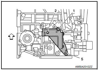
 : Front
- Tighten bolts in the numerical order as shown.
- Refer to the following for the installation positions of bolts.
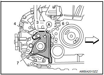
 : Front
M10 bolts : No. 1, 2, 3, 4 48.0 N·m (4.9 kg-m,
35 ft-lb)
M12 bolt : No. 5 97.1 N·m (9.9 kg-m,
72 ft-lb)
M8 bolts : No. 6, 7 25.0 N·m (2.6 kg-m,
18 ft-lb)
- Clean the matching surface of wheel hub lock nut and wheel hub and bearing.
CAUTION: Do not apply lubricating oil to these matching surface.
- Clean the mating surfaces of the joint sub-assembly and the
wheel hub and bearing. Apply molykote m77 lubricant to the surface
(a) of the joint sub-assembly.
Caution: apply lubricant to cover the entire flat mating surface of the joint sub-assembly.
Amount of lubricant FAX-65, "Drive Shaft"
NOTE: Always check with the Parts Department for the latest parts information.
- Use the following torque range for tightening the wheel hub lock nut.
CAUTION:
- Since the drive shaft is assembled by press-fitting, use the tightening torque range for the wheel hub lock nut.
- Be sure to use torque wrench to tighten the wheel hub lock nut. Do not use a power tool.
- Do not reuse wheel hub lock nut.
- Too much torque causes axle noise. Too little torque, causes wheel bearing looseness. Tighten the wheel hub lock nut to the specification.
- Align the matching marks that have been made during removal when reusing the disc brake rotor.
- When installing a cotter pin (1) and adjusting cap (2), securely
bend the cotter pin to prevent rattles.
CAUTION: Do not reuse cotter pin.
- Perform the final tightening of each of parts under unladen conditions, which were removed when removing wheel hub and bearing and steering knuckle.
- Installation of the remaining components is in the reverse order of removal.
Inspection
INSPECTION AFTER REMOVAL
- Move joint up/down, left/right, and in the axial directions. Check for motion that is not smooth and for significant looseness.
- Check boot for cracks, damage, and leakage of grease.
- ssemble drive shaft and exchange malfunctioning part if there is a non-standard condition.
INSPECTION AFTER DISASSEMBLY
Shaft
Check shaft for runout, cracks, or other damage. Replace if there are.
Dynamic Damper
Check damper for cracks or wear. Replace if necessary.
Joint Sub-Assembly (Wheel Side)
Check the following:
- Joint sub-assembly for rough rotation and excessive axial looseness
- The inside of the joint sub-assembly for entry of foreign material
- Joint sub-assembly for compression scars, cracks, and fractures inside of joint sub-assembly
Replace joint sub-assembly if there are any non-standard conditions of components.
Housing and Spider assembly (Transaxle Side)
Replace housing and spider assembly if there is scratching or wear of housing roller contact surface or spider roller contact surface.
NOTE: Housing and spider assembly are used in a set.
Support Bearing (Right Side)
Make sure wheel bearing rolls freely and is free from noise, cracks, pitting or wear. Replace support bearing if there are any non-standard conditions.
Support Bearing Bracket (Right Side)
Check for bending, cracks, or damage. Replace support bearing bracket if there are any non-standard conditions.
 Periodic maintenance
FRONT WHEEL HUB AND KNUCKLE
Inspection
Move the wheel hub and bearing in an axial direction by hand to verify
that looseness of wheel hub and
bearing exists. If any looseness exists, replace ...
 Unit disassembly and assembly
FRONT DRIVE SHAFT
Exploded View (LH)
Shaft
Circular clip
Dust shield
Housing
Snap ring
Spider assembly
Stopper ring
Boot
Boot band
Joint sub-assembly
...
Other materials:
Service data and specifications (SDS)
General Specification
GENERAL SPECIFICATIONS
( ): Valve timing control “ON”
Drive belt
Spark Plug
Intake Manifold
Exhaust Manifold
Camshaft
*1: Cam wear limit
*2: Total indicator reading
VALVE LIFTER
VALVE CLEARANCE
*: Approximately 80°C (176°F)
AVAIL ...
How to use the remote keyless entry
function
The remote keyless entry function can operate all
door locks using the remote keyless function of
the Intelligent Key. The remote keyless function
can operate at a distance of 33 ft (10 m) away
from the vehicle. The operating distance depends
upon the conditions around the vehicle.
The remot ...
O/D off indicator lamp
Component Function Check
1.CHECK O/D OFF INDICATOR LAMP FUNCTION
Check O/D OFF indicator lamp turns ON for approx. 2 seconds when ignition
switch turns ON.
Is the inspection results normal?
YES >> INSPECTION END
NO >> Go to TM-181, "Diagnosis Procedure".
Diagnosis Pro ...
