Nissan Rogue Service Manual: Unit disassembly and assembly
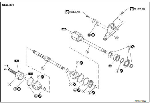
FRONT DRIVE SHAFT
Exploded View (LH)
- Shaft
- Circular clip
- Dust shield
- Housing
- Snap ring
- Spider assembly
- Stopper ring
- Boot
- Boot band
- Joint sub-assembly
 Wheel side
Disassembly and Assembly (LH)
DISASSEMBLY
Transaxle Assembly Side
- Fix shaft with a vise.
CAUTION: Protect shaft using aluminum or copper plates when fixing with a vise.
- Remove boot bands, and then remove boot from housing.
- Remove stopper ring.
- Put matching marks on housing and shaft, and then pull out housing
from shaft.
CAUTION: Use paint or an equivalent for matching marks. Do not scratch the surfaces.
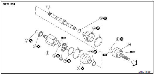
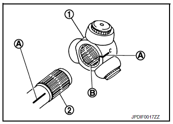
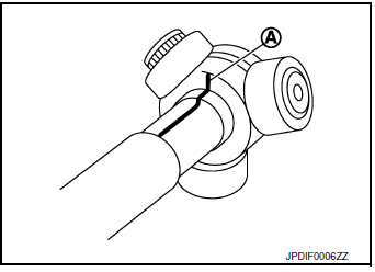
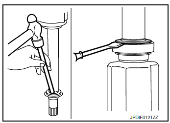
- Put matching marks (A) on the spider assembly and shaft.
CAUTION: Use paint or an equivalent for matching marks. Do not scratch the surfaces.
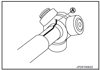
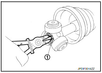
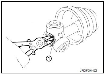
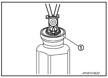
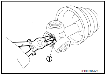
- Remove snap ring (1), and then remove spider assembly from shaft.
- Remove boot from shaft.
- Remove circular clip from housing (left side).
- Remove dust shield from housing.
- Clean old grease on housing with paper waste.
Wheel Side
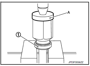
- Fix shaft with a vise.
CAUTION: Protect shaft using aluminum or copper plates when fixing with a vise.
- Remove boot bands, and then remove boot from joint sub-assembly.
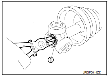
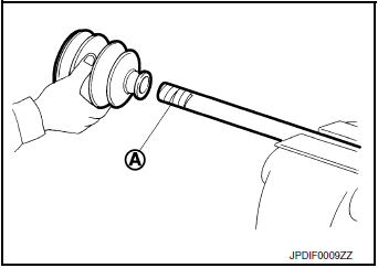
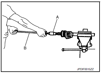
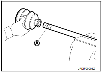
- Screw the drive shaft puller (A) 30 mm (1.18 in) or more into the thread of joint sub-assembly, and pull joint sub-assembly with a sliding hammer (B) from shaft.
CAUTION:
- If joint sub-assembly cannot be removed after five or more unsuccessful attempts, replace shaft and joint sub assembly as a set.
- Align sliding hammer and drive shaft and remove them by pulling forcibly.
- Remove circular clip from shaft.
- Remove boot from shaft.
- Clean old grease on joint sub-assembly with paper waste while rotating ball cage.
ASSEMBLY
Transaxle Assembly Side
- Install new boot and boot bands to shaft.
CAUTION:
- Wrap serration on shaft with tape (A) to protect from damage
- Do not reuse boot and boot band.
- Remove the tape wrapped around the serration on shaft.
- To install the spider assembly (1), align it with the matching marks (A) on the shaft (2) put during the removal, and direct the serration mounting surface (B) to the shaft.
- Secure spider assembly onto shaft with snap ring (1).
CAUTION: Do not reuse snap ring.
- Apply the appropriate amount of grease to spider assembly and sliding surface.
- Assemble the housing onto spider assembly, and apply the specified amount of grease.
Grease amount : Refer to FAX-32, "Drive Shaft".
- Align matching marks put during the removal of housing.
- Install stopper ring.
CAUTION: Do not reuse stopper ring.
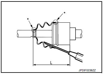
- Install boot securely into grooves (indicated by “*” marks)
shown.
CAUTION: If grease adheres to the boot mounting surface (indicated “*” mark) on shaft or housing, boot may be removed.
Remove all grease from the boot mounting surface.
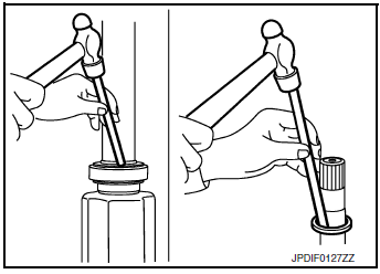
- To prevent the deformation of the boot, adjust the boot installation length (L) to the value shown below by inserting the suitable tool into the inside of boot from the large diameter side of boot and discharging inside air.
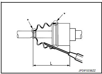
Boots installed length (L) : Refer to FAX-32, "Drive Shaft".
CAUTION:
- If the boot installation length is outside the standard, it may cause breakage of boot.
- Be careful not to touch the inside of the boot with the tip of tool.
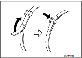
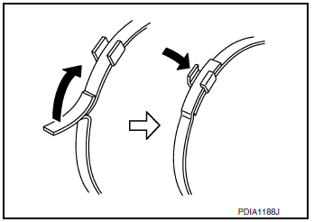
- Install new boot bands securely as shown.
CAUTION: Do not reuse boot band.
- Secure housing and shaft, and then make sure that they are in the correct position when rotating boot. Reinstall them with new boot bands when the mounting positions become incorrect.
- Install dust shield to housing (left side).
CAUTION: Do not reuse dust shield.
- Install circular clip to housing (left side).
CAUTION: Do not reuse circular clip.
Wheel Side
For further details, refer to the installation procedure of “FAX-13, "WHEEL SIDE : Removal and Installation"” for the drive shaft boot.
Exploded View (RH)
- Joint sub-assembly
- Circular clip
- Boot band
- Boot
- Shaft
- Damper band
- Dynamic damper
- Stopper ring
- Spider assembly
- Snap ring
- Housing
- Dust shield
- Support bearing
- Retainer
- Support bearing bracket
 : Wheel side
Disassembly and Assembly (RH)
DISASSEMBLY
Transaxle Assembly Side
- Fix shaft with a vise.
CAUTION: Protect shaft using aluminum or copper plates when fixing with a vise.
- Remove boot bands, and then remove boot from housing.
- Remove stopper ring.
- Put matching marks on housing and shaft, and then pull out housing
from shaft.
CAUTION: Use paint or an equivalent for matching marks. Do not scratch the surfaces.
- Put matching marks (A) on the spider assembly and shaft.
CAUTION: Use paint or an equivalent for matching marks. Do not scratch the surfaces.
- Remove snap ring (1), and then remove spider assembly from shaft.
- Remove boot from shaft.
- Remove circular clip from housing (left side).
- Remove dust shield from housing.
- Clean old grease on housing with paper waste.
Support Bearing
- Remove dust shield from housing.
- Remove snap ring (1).
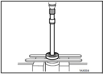
- Press out support bearing from housing.
- Remove dust shield.
Wheel Side
- Fix shaft with a vise.
CAUTION: Protect shaft using aluminum or copper plates when fixing with a vise.
- Remove boot bands, and then remove boot from joint sub-assembly.
- Screw the drive shaft puller (A) 30 mm (1.18 in) or more into the thread of joint sub-assembly, and pull joint sub-assembly with a sliding hammer (B) from shaft.
CAUTION:
- If joint sub-assembly cannot be removed after five or more unsuccessful attempts, replace shaft and joint sub assembly as a set.
- Align sliding hammer and drive shaft and remove them by pulling forcibly.
- Remove circular clip from shaft.
- Remove boot from shaft.
- Clean old grease on joint sub-assembly with paper waste while rotating ball cage.
ASSEMBLY
Transaxle Assembly Side
- Wrap serration on shaft with tape (A) to protect boot from damage.
Install new boot and boot bands to shaft.
CAUTION: Do not reuse boot and boot band.
- Remove the tape wrapped around the serration on shaft.
- To install the spider assembly (1), align it with the matching marks (A) on the shaft (2) put during the removal, and direct the serration mounting surface (B) to the shaft.

- Secure spider assembly onto shaft with snap ring (1).
CAUTION: Do not reuse snap ring.
- Apply the appropriate amount of grease to spider assembly and sliding surface.
- Assemble the housing onto spider assembly, and apply the specified amount of grease.
Grease amount : Refer to FAX-32, "Drive Shaft".
- Align matching marks put during the removal of housing.
- Install stopper ring.
CAUTION: Do not reuse stopper ring.
- Install boot securely into grooves (indicated by “*” marks) shown
in the figure.
CAUTION: If grease adheres to the boot mounting surface (indicated “*” mark) on shaft or housing, boot may be removed.
Remove all grease from the boot mounting surface.
- To prevent the deformation of the boot, adjust the boot installation length (L) to the value shown below by inserting the suitable tool into the inside of boot from the large diameter side of boot and discharging inside air.
Boots installed length (L) : Refer to FAX-32, "Drive Shaft".
CAUTION:
- If the boot installation length is outside the standard, it may cause breakage of boot.
- Be careful not to touch the inside of the boot with the tip of tool.
- Install new boot bands securely as shown in the figure.
CAUTION: Do not reuse boot band.
- Secure housing and shaft, and then make sure that they are in the correct position when rotating boot. Reinstall them with new boot bands when the mounting positions become incorrect.
- Install dust shield to housing (left side).
CAUTION: Do not reuse dust shield.
- Install circular clip to housing (left side).
CAUTION: Do not reuse circular clip.
Support Bearing
- Install dust shield on housing.
CAUTION: Do not reuse dust shield.
- Press support bearing (1) onto housing to using the suitable tool (A).
- Install snap ring.
CAUTION: Do not reuse snap ring.
- Install dust shields. CAUTION: Do not reuse dust shields.
Wheel Side
For further details, refer to the installation procedure of “FAX-13, "WHEEL SIDE : Removal and Installation"” for the drive shaft boot.
 Removal and installation
FRONT WHEEL HUB
Exploded View
Disc brake rotor
Nut retainer
Cotter pin
Wheel stud
Steering knuckle
Splash guard
Wheel hub and bearing
Wheel hub lock n ...
 Service data and specifications (SDS)
Wheel Bearing
Drive Shaft
Drive Shaft Specifications
*Always check with the Parts Department for the latest parts information.
Dynamic Damper Specifications
Boot Band Specification
...
Other materials:
Symptom diagnosis
COMBINATION SWITCH SYSTEM SYMPTOMS
Symptom Table
Perform the data monitor of CONSULT to check for any malfunctioning
item.
Check the malfunction combinations.
Identify the malfunctioning part from the agreed combination and repair
or replace the part.
NORMAL OPERATING C ...
Front power window switch (passenger side)
Description
Front power window motor RH will be operated if front power window switch RH
is operated.
Component Function Check
1. CHECK FRONT POWER WINDOW SWITCH RH FUNCTION
Check front power window motor RH operation with front power window switch RH.
Is the inspection result normal?
YES ...
P0112, P0113 IAT sensor
DTC Description
DTC DETECTION LOGIC
DTC No.
CONSULT screen terms
(Trouble diagnosis content)
DTC detecting condition
P0112
IAT SEN/CIRCUIT- B1
(Intake air temperature sensor 1 circuit low
bank 1)
An excessively low voltage from the intake air temperature sensor ...
