Nissan Rogue Service Manual: System description
SYSTEM
System Description
SYSTEM DIAGRAM
SYSTEM DESCRIPTION
- The BCM has a CAN gateway function.
- The BCM communicates between two CAN communication circuits.
- The BCM selects and transmits only necessary information.
DIAGNOSIS SYSTEM (CAN GATEWAY)
CONSULT Function
APPLICATION ITEM
CONSULT performs the following functions via CAN communication with CAN gateway.
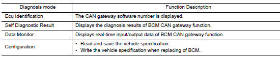
ECU IDENTIFICATION
The CAN gateway part number is displayed.
SELF DIAGNOSTIC RESULT
Refer to LAN-76, "DTC Index".
- When “CRNT” is displayed on self-diagnosis result
- The system is presently malfunctioning.
- When “PAST” is displayed on self-diagnosis result
- System malfunction in the past is detected, but the system is presently normal.
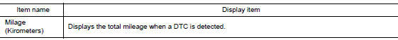
Freeze Frame Data (FFD)
When DTC is detected, a vehicle state shown below is recorded and displayed on CONSULT.
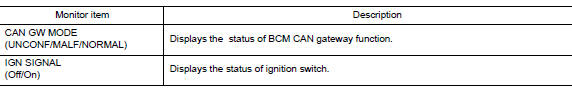
DATA MONITOR
CONFIGURATION
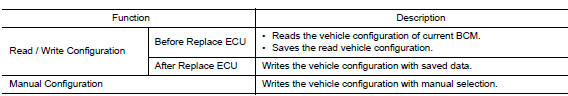
CAUTION: Follow the instructions listed below. Failure to do this may cause malfunctions to the BCM.:
- When replacing BCM you must perform “Read / Write Configuration” or “Manual Configuration” with CONSULT.
- Complete the procedure of “Read / Write Configuration” or “Manual Configuration” in order.
- If you set incorrect “Read / Write Configuration” or “Manual Configuration”, incidents might occur.
- Configuration is different for each vehicle model. Confirm configuration of each vehicle model.
- Never perform “Read / Write Configuration” or “Manual Configuration” except for new BCM.
 Precaution
Precaution for Supplemental Restraint System (SRS) "AIR BAG" and "SEAT
BELT
PRE-TENSIONER"
The Supplemental Restraint System such as “AIR BAG” and “SEAT BELT PRE-TENSIONE ...
 ECU diagnosis information
CAN GATEWAY
Reference Value
VALUES ON THE DIAGNOSIS TOOL
NOTE:
The following table includes information (items) inapplicable to this vehicle.
For information (items) applicable
to this vehicle, ...
Other materials:
Heated seat switch
Exploded View
Center console cup holder
Driver heated seat switch
Passenger heated seat switch
Switch carrier
Pawl
Removal and Installation
REMOVAL
Remove the center console cup holder. Refer to IP-18, "Exploded
View".
Remove screws fro ...
Power liftgate main switch
Power liftgate main switch
The power liftgate operation can be turned on or
off by the power liftgate main switch on the
instrument panel.
When the power liftgate main switch is pushed to
the OFF position, the power operation is not
available by the power liftgate switch on the
liftgate ...
Door mirror
Exploded View
Door mirror
Door mirror corner finisher
Door mirror rear finisher
Side turn signal lamp
Side camera (if equipped)
Door mirror glass
Pawl
Removal and Installation
REMOVAL
Remove front door finisher. Refer to INT-15, "Removal and
...
