Nissan Rogue Service Manual: Door mirror
Exploded View

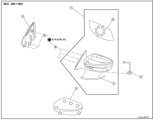
- Door mirror
- Door mirror corner finisher
- Door mirror rear finisher
- Side turn signal lamp
- Side camera (if equipped)
- Door mirror glass
 Pawl
Pawl
Removal and Installation
REMOVAL
- Remove front door finisher. Refer to INT-15, "Removal and Installation".
- Release door mirror corner finisher clips using a suitable tool.
- Disconnect the harness connector from the blind spot warning indicator (if equipped), then remove the door mirror corner finisher.
- Disconnect the harness connector from the door mirror.
- Remove door mirror nuts and door mirror.
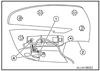
- Remove screws (A) and side camera (1) (if equipped) (if necessary)
from door mirror rear finisher (2).
 : Pawl

INSTALLATION
Installation is in the reverse order of removal.
CAUTION: Perform camera image calibration (if equipped with around view camera). Refer to AV-136, "CALIBRATING CAMERA IMAGE (AROUND VIEW MONITOR) : Work Procedure".
 Inside mirror
Exploded View
MANUAL ANTI-DAZZLING
Windshield glass
Mirror base
Inside mirror
AUTO ANTI-DAZZLING
Windshield glass
Mirror base
Inside mirror
Inside mirror finish ...
 Door mirror glass
Removal and Installation
REMOVAL
Release the metal clips and pawls that retain the door mirror
glass using a suitable tool, disconnect the harness connectors
(A) (if equipped) from the ...
Other materials:
Refrigeration system symptoms
Trouble Diagnosis For Unusual Pressure
Diagnose using a manifold gauge whenever system’s high and/or low side
pressure(s) is/are unusual. The
marker above the gauge scale in the following tables indicates the standard
(usual) pressure range. Refer to
above table (Ambient air temperature-to- ...
Wiring diagram
POWER WINDOW SYSTEM
Wiring Diagram
...
P0776 pressure control solenoid B
DTC Description
DTC DETECTION LOGIC
DTC
CONSULT screen terms
(Trouble diagnosis content
DTC detection condition
P0776
PC SOLENOID B
(Pressure Control Solenoid “B” Performance/
Stuck Off)
When any of 1 or 2 is satisfied and this state is maintained for 10
...
