Nissan Rogue Service Manual: Inside mirror
Exploded View
MANUAL ANTI-DAZZLING
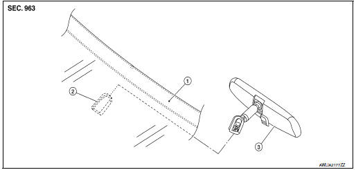
- Windshield glass
- Mirror base
- Inside mirror
AUTO ANTI-DAZZLING
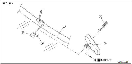
- Windshield glass
- Mirror base
- Inside mirror
- Inside mirror finisher
- Harness connector
- Bolt
Removal and Installation
MANUAL ANTI-DAZZLING
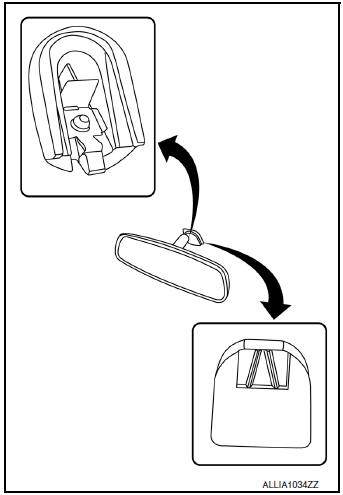
Removal
- Hold inside mirror at the base and push upward, while using a suitable tool to release the pawl and remove.
CAUTION: Use care when removing inside mirror to avoid damage to mirror, mirror base or windshield glass.
Installation
Installation is in the reverse order of removal.
CAUTION: Apply Genuine Mirror Adhesive or equivalent to bonding surface of mirror base if loose or removed.
Refer to GI-22, "Recommended Chemical Products and Sealants".
AUTO ANTI-DAZZLING
Removal
- Remove inside mirror finisher.
- Disconnect the harness connector from the inside mirror.
- Loosen bolt and slide inside mirror upward to remove.
Installation
Installation is in the reverse order of removal.
- Calibrate compass (if equipped).
CAUTION: Apply Genuine Mirror Adhesive or equivalent to bonding surface of mirror base if loose or removed.
Refer to GI-22, "Recommended Chemical Products and Sealants".
NOTE: Calibrate the compass by driving the vehicle in a complete circle three times.

 Door mirror
Exploded View
Door mirror
Door mirror corner finisher
Door mirror rear finisher
Side turn signal lamp
Side camera (if equipped)
Door mirror glass
Pawl
Removal an ...
Other materials:
Wiring diagram
TIRE PRESSURE MONITORING SYSTEM
Wiring Diagram
...
Front wiper motor HI circuit
Component Function Check
1.CHECK FRONT WIPER HI OPERATION
CONSULT ACTIVE TEST
Select FR WIPER of BCM (WIPER) active test item.
Check front wiper operation.
HI : Front wiper (HI) operation
OFF : Front wiper OFF
Is the inspection result normal?
YES >> Front wiper motor ...
Removal and installation
STARTER MOTOR
Exploded View
REMOVAL
Transaxle assembly
Starter motor
Lower bolt
Upper bolt
Removal and Installation
REMOVAL
Remove battery tray. Refer to PG-77, "Removal and Installation".
Remove terminal B nut and terminal B harness.
R ...
