Nissan Rogue Service Manual: Removal and installation
IPDM E/R (INTELLIGENT POWER DISTRIBUTION MODULE ENGINE ROOM)
Exploded View
- IPDM E/R cover
- IPDM E/R
- IPDM E/R case
- IPDM E/R harness cover A
- IPDM E/R harness cover B
 Front
Front
Removal and Installation
CAUTION: IPDM E/R integrated relays are not serviceable parts, do not remove from the IPDM E/R.
REMOVAL
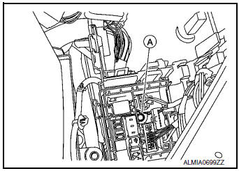
- Disconnect the negative battery terminal. Refer to PG-75, "Removal and Installation (Battery)".
- Remove air duct (inlet). Refer to EM-24, "Exploded View".
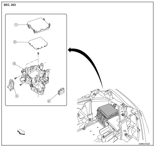
- Release pawls on IPDM E/R cover (1) and remove.
 : Pawls
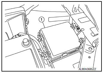
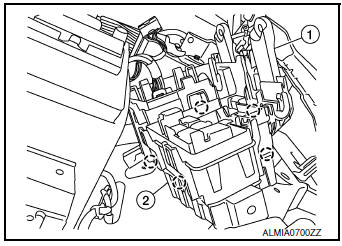
- Release pawls and remove IPDM E/R (1) from the IPDM E/R
case (2).
 : Pawls
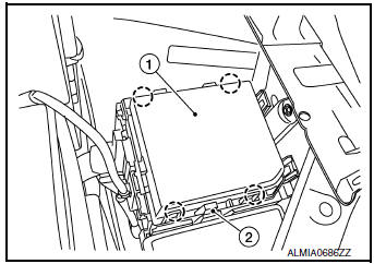
- Disconnect the harness connectors from IPDM E/R (1).
CAUTION: Replace the IPDM E/R if it has been dropped or sustained an impact.
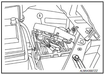
- Release the negative battery cable and harness clips from the IPDM E/R case.
- Release the pawls on the IPDM/ E/R harness covers A, B and remove from the IPDM E/R case.
- Remove the bolts from the IPDM E/R case.
- Remove the bolt (A) from the fusible link box (battery).
- Release the pawls on the fusible link box (battery) case (2) and
remove from the IPDM E/R case (1).: Pawls
INSTALLATION
Installation is in the reverse order of removal.
 DTC/circuit diagnosis
U1000 CAN COMM CIRCUIT
Description
Refer to LAN-8, "System Description".
DTC Logic
DTC DETECTION LOGIC
CONSULT Display
DTC Detection Condition
Possible Cause
...

Other materials:
Brake warning lamp
Component Function Check
1.CHECK BRAKE WARNING LAMP FUNCTION
Check that brake warning lamp in combination meter turns ON for 1 second
after ignition switch is turned ON.
CAUTION:
Never start the engine.
Is the inspection result normal?
YES >> GO TO 2.
NO >> Proceed to BRC-12 ...
Checking engine oil level
Checking engine oil level
Park the vehicle on a level surface and apply
the parking brake.
Start the engine and let it idle until it reaches
operating temperature.
Turn off the engine. Wait more than
10 minutes for the oil to drain back into
the oil pan.
Remov ...
Power switch illumination circuit
Description
Provides the power supply and the ground to control the power switch
illumination.
Component Function Check
1.CHECK POWER SWITCH ILLUMINATION OPERATION
CONSULT ACTIVE TEST
Turn the power switch ON.
Select ŌĆ£ENGINE SW ILLUMIŌĆØ of ŌĆ£BCMŌĆØ active test item.
&n ...
