Nissan Rogue Service Manual: Power switch illumination circuit
Description
Provides the power supply and the ground to control the power switch illumination.
Component Function Check
1.CHECK POWER SWITCH ILLUMINATION OPERATION
 CONSULT ACTIVE TEST
- Turn the power switch ON.
- Select ŌĆ£ENGINE SW ILLUMIŌĆØ of ŌĆ£BCMŌĆØ active test item.
- With operating the test items, check that the power switch illumination turns ON/OFF.
On : Power switch illumination ON
Off : Power switch illumination OFF
Does the power switch illumination turn ON/OFF? YES >> Power switch illumination circuit is normal.
NO >> Refer to INL-52, "Diagnosis Procedure".
Diagnosis Procedure
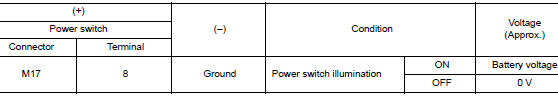
1.CHECK POWER SWITCH ILLUMINATION POWER SUPPLY OUTPUT
- Turn power switch OFF.
- Disconnect power switch connector.
- Check voltage between power switch harness connector and ground.
Is the inspection result normal? YES >> GO TO 4.
NO >> GO TO 2.
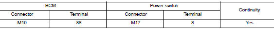
2.CHECK POWER SWITCH ILLUMINATION POWER SUPPLY OPEN CIRCUIT
- Turn the power switch OFF.
- Disconnect BCM connector.
- Check continuity between BCM harness connector and the power switch harness connector.
Is the inspection result normal? YES >> GO TO 3.
NO >> Repair or replace harnesses.
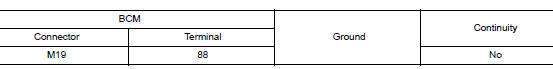
3.CHECK POWER SWITCH ILLUMINATION POWER SUPPLY SHORT CIRCUIT
Check continuity between BCM harness connector and ground.
Is the inspection result normal? YES >> Replace BCM. Refer to BCS-75, "Removal and Installation" (with intelligent Key system) or BCS- 135, "Removal and Installation" (without Intelligent Key system).
NO >> Repair or replace harnesses.
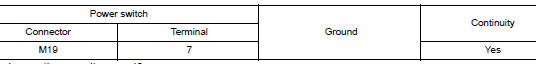
4.CHECK POWER SWITCH ILLUMINATION GROUND CIRCUIT
- Turn the power switch OFF.
- Check continuity between power switch harness connector and ground.
Is the inspection result normal? YES >> Replace power switch. Refer to SEC-112, "Removal and Installation".
NO >> Repair or replace harnesses.
 Luggage room lamp circuit
Description
Controls the luggage room lamp (ground side) to turn the luggage room lamp ON
and OFF.
Diagnosis Procedure
CAUTION:
Before performing the diagnosis, check that the following is norma ...
 Symptom diagnosis
INTERIOR LIGHTING SYSTEM SYMPTOMS
Symptom Table
CAUTION:
Perform the self-diagnosis with CONSULT before the symptom diagnosis. Perform
the trouble diagnosis
if any DTC is detected.
S ...
Other materials:
Engine cooling system
The engine cooling system is filled at the factory
with a pre-diluted mixture of 50% Genuine
NISSAN Long Life Antifreeze/Coolant (blue) and
50% water to provide year-round anti-freeze and
coolant protection. The antifreeze solution contains
rust and corrosion inhibitors. Additional engine
cool ...
C1704, C1705, C1706, C1707 low tire pressure
DTC Logic
NOTE:
The Signal Tech II Tool [- (J-50190)] can be used to perform the following
functions. Refer to the Signal Tech II
User Guide for additional information.
Activate and display TPMS sensor IDs
Display tire pressure reported by the TPMS sensor
Read TPMS DTC ...
Precaution
Precaution for Supplemental Restraint System (SRS) "AIR BAG" and "SEAT
BELT
PRE-TENSIONER"
The Supplemental Restraint System such as ŌĆ£AIR BAGŌĆØ and ŌĆ£SEAT BELT PRE-TENSIONERŌĆØ,
used along
with a front seat belt, helps to reduce the risk or severity of injury to the
...
